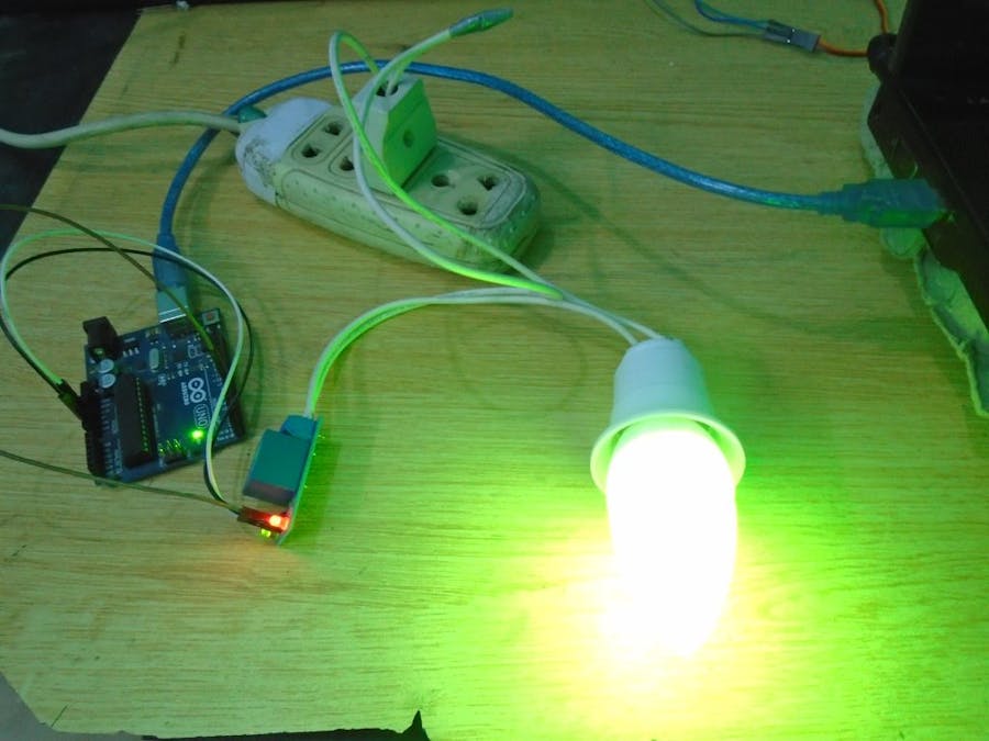
First, we will control a simple LED then we will control a light bulb using it. The Arduino can control the devices which runs on up to 5V so if we want to control the devices which runs on more than 5V or the A.C devices then we will have to use a relay module through which we can control A.C as well as DC devices.
Relay ModuleA relay is basically a switch that is operated by an electromagnet. The electromagnet requires a small voltage to get activated which we will give from the Arduino and once it is activated, it will pull the contact to make the high voltage circuit.
The relay module we are going to use is the SRD-05VDC-SL-C. It runs on 5V and we can control it with any micro-controller but we are going to use Arduino.
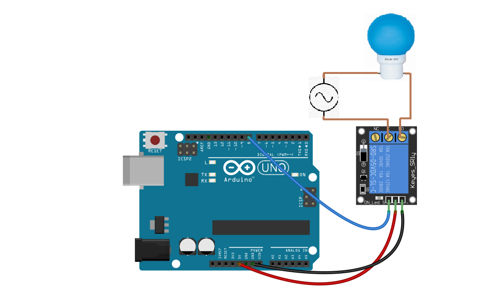
Pin out of 5V relay moduleThe Arduino relay module has total of six pins: three on one side and three on other side.On the bottom side, there are three pins which are signal, 5V and ground. We will connect these pins with the Arduino. While on the other side, there are NC (Normally close), C (Common) and the NO (normally open) which are the output pins of the 5V relay. There, we will connect the output device.
Normally open state (NO) VS Normally closed state (NC)The Arduino relay module can be used in two states which are
- Normally open state (NO)
- Normally closed state (NC)
Normally open (NO)
In the normally open state, the initial output of the relay will be low when it will be powered. In this state, the common and the normally open pins are used.
Normally closed state (NC)
In the normally closed state, the initial output of the relay will be high when it will be powered. In this state, the common and the normally close pins are used.
Controlling DC Devices using Arduino Relay ModuleIn the first part, we will control a led using the relay and in the second part we will control a high voltage device using the relay. Controlling a DC device is easy as compared to the AC device. For controlling the DC device, you do not require an external supply until you are controlling a small voltage device like LED which runs on up to 5V.
Required Components- Arduino Uno
- Relay Module
- LED
The connections for connecting the relay module with Arduino are very simple. In this example, we will connect the relay module with Arduino in the normally open state. So, connect the 5V and the ground of the Arduino with the 5V and the ground of the relay module. Then connect the signal pin of the relay module with the pin 12 of the Arduino.
On the other side of the relay module, we will use the common pin and the normally open pin because we are going to connect the relay in the normally open state. So, connect the pin 13 of Arduino to the common of relay module and the normally open (NO) of the relay module to the positive pin of the LED. Connect the other pin of LED to the ground of Arduino.
int relay_pin = 8;
int led_pin = 13;
void setup(){
pinMode(relay_pin,OUTPUT);
pinMode(led_pin,OUTPUT);
digitalWrite(led_pin,HIGH);}
void loop(){
digitalWrite(relay_pin,HIGH);
delay(5000);
digitalWrite(relay_pin,LOW);
delay(5000);
}For the control of AC device, you need to take the necessary precautions because the AC is dangerous and it can cause damage to you. So, to avoid any danger, follow the below tutorial correctly.
Required Components- Arduino Uno
- Relay Module
- Light Bulb with holder
For the control of AC device, we will require an external source which will power the AC source. So, connect the VCC, ground and signal to the 5V, ground and pin 8 of Arduino respectively. On the other end, connect one wire of the AC source to the one end of the bulb and the other wire to the common (C) of the relay. Then connect the normally open (NO) to the other end of the bulb.
Codeint relay_pin = 8;
void setup(){
pinMode(relay_pin,OUTPUT);
}
void loop(){
digitalWrite(relay_pin,HIGH);
delay(5000);
digitalWrite(relay_pin,LOW);
delay(5000);
}After making sure everything works fine on the breadboard, I have designed the PCB on KiCad.
Following is a link to the project folder of this project.
After designing the PCB’s, I generated the Gerber file needed for the manufacturing of PCB.
You can download the Gerber file through the following link
Arduino bluetooth relay gerber
Required Components- Arduino Nano
- Relay SRD-05VDC-SL-C X 4
- Terminal Block 3 pin 5.08mm X 4
- Barrel Jack
- 1N4007 Diode X 5
- LED Red
- LED Green X 4
- BC547 X 4
- Resistor 1k X 5
- Resistor 220ohm X 5
- Resistor 2k
- Switch 3 pin
Now we have got the PCB design and it’s time to order the PCB’s. For that, you just have to go to JLCPCB.com, and click on “QUOTE NOW” button.
JLCPCB are also sponsor of this project. JLCPCB (Shenzhen JLC Electronics Co., Ltd.), is the largest PCB prototype enterprise in China and a high-tech manufacturer specializing in quick PCB prototype and small-batch PCB production. You can order a minimum of 5 PCBs for just $2.
To get the PCB manufactured, upload the gerber file you downloaded in the last step. Upload the.zip file or you can also drag and drop the gerber files.
After uploading the zip file, you’ll see a success message at the bottom if the file is successfully uploaded.
You can review the PCB in the Gerber viewer to make sure everything is good. You can view both thetop and bottom of the PCB.
After making sure our PCB looks good, we can now place the order at a reasonable price. You can order 5 PCBs for just $2 but if it’s your first order then you can get 10 PCBs for $2.
To place the order, click on “SAVE TO CART” button.
My PCBs took 2 days to get manufactured and arrived within a week using DHL delivery option. PCBs were well packed and the quality was really good.
After assembling everything here is how it looks like.
int relay1_pin = 6;
int relay2_pin = 7;
int relay3_pin = 8;
int relay4_pin = 9;
void setup() {
pinMode(relay1_pin, OUTPUT);
pinMode(relay2_pin, OUTPUT);
pinMode(relay3_pin, OUTPUT);
pinMode(relay4_pin, OUTPUT);
digitalWrite(relay1_pin, LOW);
digitalWrite(relay2_pin, LOW);
digitalWrite(relay3_pin, LOW);
digitalWrite(relay4_pin, LOW);
}
void loop() {
digitalWrite(relay1_pin, HIGH);
delay(1000);
digitalWrite(relay2_pin, HIGH);
delay(1000);
digitalWrite(relay3_pin, HIGH);
delay(1000);
digitalWrite(relay4_pin, HIGH);
delay(1000);

digitalWrite(relay4_pin, LOW);
delay(1000);
digitalWrite(relay3_pin, LOW);
delay(1000);
digitalWrite(relay2_pin, LOW);
delay(1000);
digitalWrite(relay1_pin, LOW);
delay(1000);
}If you have any questions, feel free to ask us in the comment section.


Comments