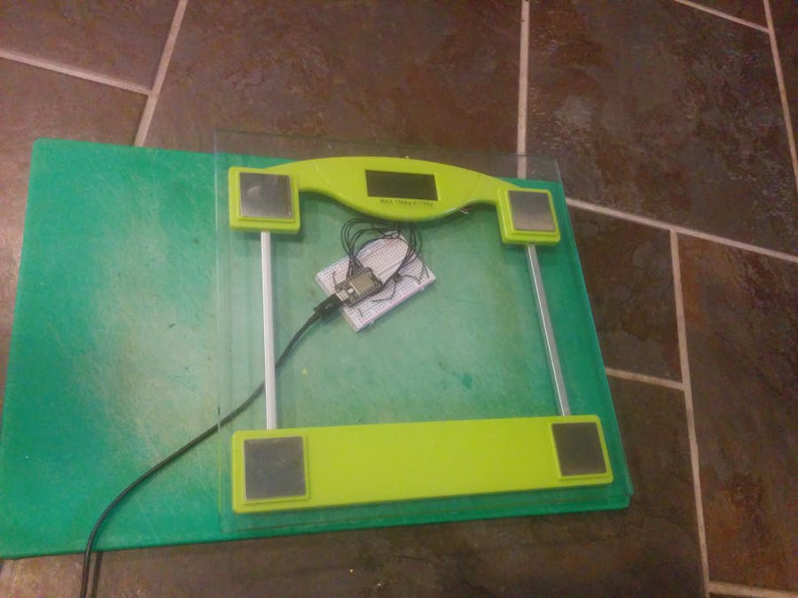
My partner has some Fitbit Aria scales which got me really into logging my weight, but she took them away recently and I had to revert back to using some old scales that just weren't smart enough for me. So I set about using a Particle Core to give them a little more functionality.
There are a few good write-ups of other people doing this around the web, some using Arduinos. The most useful one that I found was by Dušan Stojković here. I am indebted to him for sharing his work as it made my life a lot easier.
There are two common methods that people use to hack into scales: either reading the strain gauges yourself through some circuitry into an analogue input, or by tapping into the LCD display and reading that. I chose the second method, as I wanted to retain the existing display components, and I was concerned that reading the strain gauge would bias the input to those.
Connecting to the ScaleI'm not sure of the make and model of the scales I used, as they had been kicking around the house for a while. Unscrewing the back of them to get inside was straightforward, revealing a small circuit board powered by a CR2032 coin battery and connected to a 7-segment LCD display. The battery was good news, as this meant I could power the whole thing from the Particle Spark Core that I was planning to use for the project.
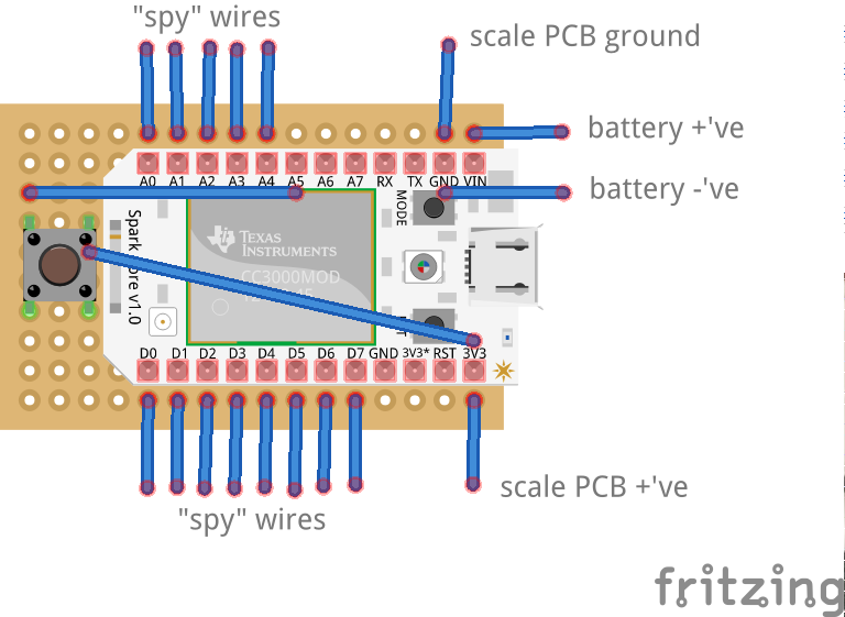
With the circuit board I was not as lucky as Dušan though, as there were no test points for me to solder my "spy" wires to. Instead I carefully soldered them onto the pads the LCD connector presses against, as shown below.
Not shown are two more wires that I added so that I could power the circuit board from the Core, rather than from the coin battery holder (attached to the back of the board).
The LCD connector was a little squishy and pressed onto the soldered wires instead of the pads and still worked. Where the LCD and the circuit board sit are shown in the next picture.
With the LCD and the circuit board back in place I was able to connect the spy wires to my Core on a breadboard. Luckily the breadboard fitted underneath the scales without fouling it, so I was able to test the whole thing.
I was able to use the digital output on the Core to drive the LCD and figure out what connections I had. I recommend you follow the descriptions and links from Dušan's page to understand how the LCD works with backplanes and the like. Mine was a little different to his, having 4 backplanes rather than 3, resulting in less wires overall.
Powering the Core from USB, and the scales from the Core, I was able to quickly test my code. Serial logging was essential here to see what was going on. I built up my code borrowing some parts from Dušan, modifying it to work with my scales, and then improving it where I could.
I read from the spy wires repeatedly for a number of loops and then take the average of these readings to get the displayed value. I monitor the displayed value to see when it settles to a steady value. Once it has settled I log the reading.
Maximising Battery LifeIn order to maximize battery life I put the Core to sleep in between uses. It wakes up when the LCD turns on, but does not connect to wifi immediately. It only connects to wifi once a reading is ready to log. There are some timeouts that put it back to sleep after logging or if no reading comes in.
One issue I had whilst testing was that in order to program the Core over wifi I needed the wifi to remain connected for longer than it would sensibly be connected for whilst in use as a scale. I therefore added a small push button that can be pressed to connect to wifi and massively increase the sleep timeout value, without needing a settled value. This allows new programs to be flashed without requiring a direct USB connection to the Core using DFU mode.
Putting it Back TogetherOnce I had it all working and was happy with my connections I made them permanent by replacing the breadboard with a bit of matrix board and soldering everything in place.
The fly wires on the bottom of the board are to connect in the button. Also shown are the power wires being fed down the tube to the bottom half of the scale where I could mount the larger batteries needed to power the Core. By trimming down the pins and some corners of the board I was able to squeeze the matrix board into the small gap next to the LCD in the scale case and refit the back.
The new button on the matrix board to increase the wifi timeout is just visible under the case and can just be reached with the battery cover off. The Core board sits just under the "Q.C. Passed" sticker.
With all of that installed and working the final part was to add in some batteries as the original coin battery was not really big enough to power the wifi and give a reasonable lifespan. Fortunately I found that the bottom half of the scales that houses the lower two strain gauges had quite a bit of space left in it. I was able to squeeze two double AAA battery holders in here, connected to the Core via a couple of wires in one of the tubes that already carried the strain gauge wires.
The Core code publishes the final weight over wifi; this then needs to be collected and logged. I have set this up through If This Then That (IFTTT), which has a Particle channel. There are loads of possibilities from here, but I chose to simply log each weight as a new row in a Google sheet. Conveniently I can use the same sheet that I use for the Fitbit Aria logs, so that I can still gather those when I visit my partner.
Unfortunately I've found that the Particle channel of IFTTT can be a bit temperamental and therefore I've tried to set up direct logging to a Google sheet using Particle webhooks. This should all work well, but unfortunately the Google form that can be used to POST data to a new row in a sheet uses periods in its form field names, and there is currently a bug in the webhook server side code that gives an error for these. Hopefully once this is corrected it should work a lot more smoothly.


_3u05Tpwasz.png?auto=compress%2Cformat&w=40&h=40&fit=fillmax&bg=fff&dpr=2)
Comments
Please log in or sign up to comment.