The Light Badge is an electronic kit which utilizes an LDR (light dependent resistor) to detect lowering light levels and light a LED once it gets dark.This is a great example of an LDR in action.
An LDR (light dependent resistor) or photoresistor is a resistor where the resistance decreases with the strength of the light.
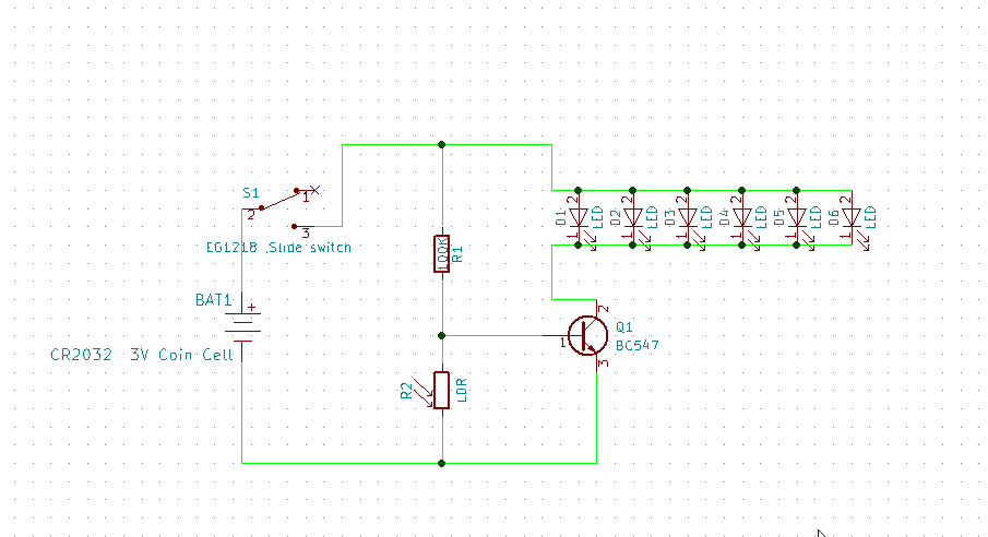
Schematics:
This is how the circuit works: When exposed to bright light, the photoresistor’s resistance is very low.It drops to around 20-30 KΩ.Current travels through the 100 KΩ resistor and then has 2 paths.It can either go through the base of the transistor or go through the photoresistor. The base of transistor to the collector has a resistance of around 400 KΩ.Current always takes the path of least resistance. When photoresistor is exposed to bright light, its resistance is about 20-30 kΩ, which is significantly less than the 400 kΩ of resistance the base of the transistor has.Therefore, most of the current will go through the photoresistor and very little will go to the base of the transistor. So the base of the transistor is bypassed, Thus, the transistor does not receive enough current to turn on and power on the LED.Thus the LED is off when there is lot of light in the surroundings.
When it is dark, photoresistor’s resistance becomes very high.It’s resistance goes up to 2 MΩ.This creates a very high resistance path, due to this, most of the current will go through the base of the transistor. Means that current does not go through the photoresistor when it is dark.
In the above circuit LDR and the 100 k resistor form a simple ‘potential divider’ circuit, where the middle point of the potential divider is fed to the base of the NPNtransistor. Therefore based on light intensity the brightness of LEDs will be changed.
Note: On the PCB I have represented anode of led with small white dotted silkscreen.
All the Project files are up on GitHub, go make!


Comments
Please log in or sign up to comment.