One of the big problems that exists in the area of creating projects with Microcontrollers, is the power supply of the project. I'm sure you already suffered when there was a power outage in the power grid and the project stopped processing information.
In some microcontrollable designs, for example, security systems, lighting resources and sensor data processing may stop working, and to avoid this problem, a circuit is required to ensure the maintenance of electrical energy.The circuit of the Backup Battery
To avoid this problem, I want to propose a simple circuit and low cost, to ensure electrical power for your electronic projects.
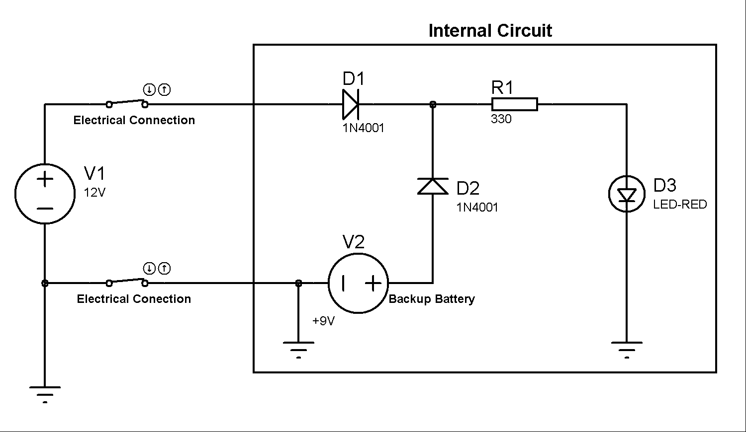
As you can see in Figure 1, we have power supplies. The V1 power supply is used to represent the main power source of the electrical circuit. The V2 power supply is our backup battery.
It is used to supply electrical power to the LED when the V1 power source is not connected. The LED is used to represent the charge of the circuit, but you can change for anyone other electronic device, for example, thepresence sensor, security system, and others.
Circuit OperationWhen the voltage source V1 is connected to the electrical circuit, the diode D1 is directly polarized and the diode D2 is inversely polarized. In this first case, the electric current will flow through the diode D1.
In the second case, as is presented in Figure 2, when the V1 power supply is disconnected or occur power outage, the diode D1, don't will conduce.
At this moment, the diode D1 begins conducts the electrical current, because it is directly polarized, so the LED continues energized.
When the voltage source V1 is connected again, the D1 diode will conduct again and the D2 diode will be inversely polarized.
AcknowledgmentThanks to the PCBWay for support the our YouTube Channel and produce and assembly PCBs with better quality.
The Silícios Lab thanks UTSOURCE to offer the electronic components.


Comments
Please log in or sign up to comment.