In this project, my father and I are taking a shot to improve our own spot welder, which we started around two years ago. It might not be a hot topic on this website, but we had fun making it and learned a lot out of it. We hope you do as well.
What I am covering in this projectI will only cover the Arduino part of the welder, which is simple and does its job quite well, as well as give some basic specs of the welder itself. There are many turorials on YouTube and electronics forums that cover the making process of a welder and that is how we learned as well.
What is a spot welder?It is a device that forces a large current to a small spot between metals, thus meting them and joining them together, from the heat that is generated. This process lasts some mere milliseconds (depending on the metals that we're welding) and requires the device to be highly powered, which is the main feature of a spot welder: Delivering high power in a very short time.
To deliver this current, copper alloy electrodes are used.
How to decide how much time this process will last?In my opinion, there is no standard when it comes to welding time. Me and my father, only use our experience to decide how many milliseconds are enough for a good welding, although, this time can be calculated easily, given the power of the welder and the thickness of the metals we are about to join together.
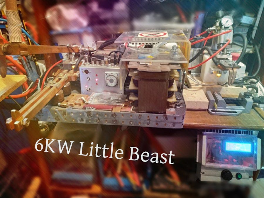
Components / basic specsWe use 4x1.5kW transformers to provide the power we need for our weldings, which gives us a theoretical power of 6kW. We got these transformers from truck battery chargers. In order to make them usable for our welder, we must remove their secondary windings, add two spires of welding cable (CH01N2-D) and connect all transformers in parallel. They must share the same phase, otherwise the circuit will be shorted. The welder has two means of welding:
- The classic copper electrodes (left side of Image 1).
- The "spider's teeth": an add-on that is used to weld batteries and it works with pressurized air (right side of Image 1).
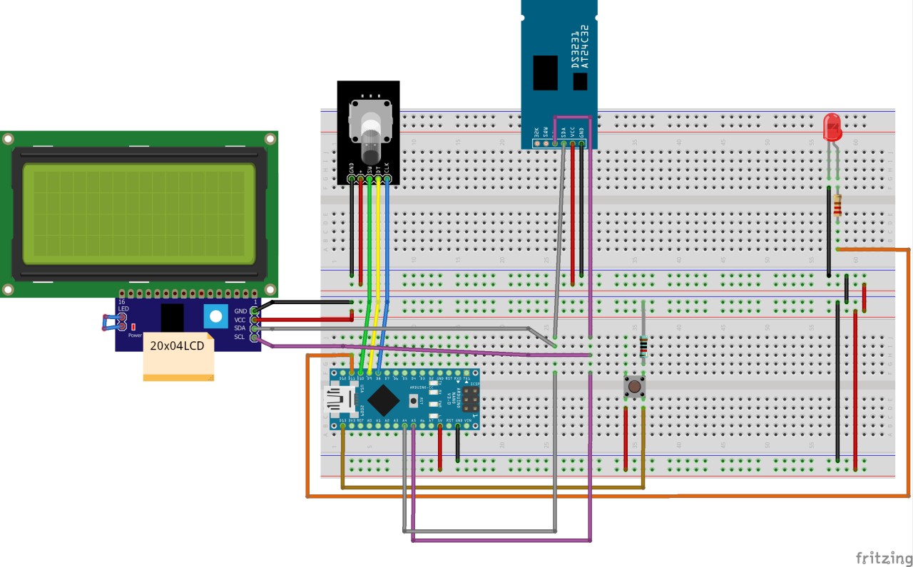
As seen on Image 2, our board is very easy to understand:
- The Arduino Nano takes center stage, and the most space on the board.
- We use a DS3231 Real-Time Clock module, to display the date/time and to use it for timing purposes as well. (Library: http://www.rinkydinkelectronics.com/library.php?id=73)
- We use a 20x4 LCD screen, which can fit more information than a much more used 16x2 LCD (we actually used that in our previous build, see second YouTube video at the end of the project's description). Here's a link to download the library (Wayback Machine link, takes a while to load, original Git was deleted): https://web.archive.org/web/20200720122215/https://bitbucket.org/fmalpartida/new-liquidcrystal/downloads/. I am using the 1.3.5 version in this project.
- In order to be able to navigate through the menu, we use a rotary encoder, which saves a lot of space and complexity.
- Last but not least, we have the weld button along with its 10KΩ resistor.
The output of the Nano, can then be used to guide a solid state relay, which in its turn, guides the rest of the welder.
Order boardIf you want to order the board from a PCB manufacturer instead of making it yourself, grab the gerber file from the repository: https://github.com/SauROnmiKE/Master_Welder
Go into the "Gerber" folder and download the "MASTER_WELDER.zip" file there, this is the gerber file for the board. Upload this file to the manufacturer's website when you give information about the board (most, if all of them SHOULD have this option) and continue from there.
As seen on Image 1, the circuit is enclosed. We do not have to modify it in any way, we just use the rotary encoder and the pushbutton.
The programThe program is very simple and honestly, a small part of it was made to correct some aesthetic changes that made the program's visual appeal bad.
As explained in the video (Timestamp: 03:03 - 04:57), when the Nano powers, we can see the default values that are used. In order to change these values, we must enter the "Options Mode". In order to do that, we must press the pushbutton of the rotary encoder for 2 seconds (you can change that to whatever you like from the source code). Once we do that, an "!" will appear in the top right corner of the LCD and will disappear automatically, once we enter Options Mode.
From now on, we can edit any value we need, using the rotary encoder. When we're happy with the values we entered, we again push the rotary encoder for 2 seconds and we are now ready to weld.
YouTube VideoIn the video above, you can get some more info about the welder and see it in action.
Old buildIn the video below, we tested the older version of our spot welder, which had less power and was lacking some of the features the current build has. It is a good view though if you want to see more, as we give some tips about welding.
(NOTE: The audio is in Greek, but there are English subs as well.)
THANK YOUThank you for taking the time to check our creation. We had fun making it and we hope you did too watching it. Also, a big thank you to PCBWay for sponsoring the boards used. It was a big help. Don't forget to leave any questions if you have any and check my other projects as well. Have a nice day!


Comments
Please log in or sign up to comment.