


Hardware components | ||||||
 |
| × | 3 | |||
 |
| × | 1 | |||
 |
| × | 6 | |||
| × | 1 | ||||
| × | 1 | ||||
| × | 1 | ||||
| × | 1 | ||||
Software apps and online services | ||||||
 |
| |||||
| ||||||
We are all lazy.
There have been countless times where I have rushed out the door in a hurry to a class that I’m 30 minutes late for — due to oversleeping — and have forgotten to lock the door. I could also account for the times that I have been under a mountain of snacks while on the couch and someone comes to the door, resulting in me having to tumble off the couch, walk to the door, and unlock the door.
Not anymore.
The solution is a photon connected to a stepper motor that stays in front of the door lock.
AssemblyBefore construction, specific parts need to be made for the stepper motor to couple onto the lock. Two objects were designed as a modification to our door lock.
Object one is an attachment that goes directly onto the shaft of the stepper motor. This part was designed to be a tight fit, requiring no locks or set screws as you would see in a standard coupler. The opposing end had a generic shape that goes around the area of the lock just enough so that it rotates relative to the stepper motor.
Object 2 is the body (housing) of the system. This part goes over the door lock and grounds the stepper motor. Measurements were taken to design the part to fit around our lock frame which was approximately 2.10 inches.
Simplify 3D is the slicer software used to print this part, given a .stl file.
Simplicity was the goal of our project which meant that our application had to be intuitive and easy to use. Using Blynk, we were able to remotely control the stepper motor by toggling through a single button. Only two functions were needed in this design; lock and unlock.
When the button is set to "UNLOCKED", digital pin 3 is set to LOW which verifies that the door is unlocked. If the door is in a locked state prior to activating the button, the program will run through a series of IF statements until the lock has rotated a certain number of times in the counter-clockwise direction.
When the button is set to "LOCKED", digital pin 3 is set to HIGH which verifies that the door is locked. If the door is in a locked state prior to activating the button, the program will run through a series of IF statements until the lock has rotated a certain number of times in the clockwise direction.
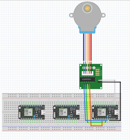
The circuit board for the stepper motor schematic is shown below. The following image after is the device attached to our front door.
The particle photons (1, 2, and 3) communicate with one another once the locking mechanism is triggered to rotate by the Blynk application on a user’s phone. A list of the line of communication and responses:
When the door is locked:
Particle 1 sends communication to Particle 2. It turns the D7 LED on. In turn, Particle 2 connects with Particle 1 (which turns its originally on LED off for 5 seconds then back on) and with Particle 3 (which turns its originally off D7 LED on).Then, Particle 3 returns communication to both Particle 1 and 2; Particle 1 blinks its LED off for 5 seconds and then back on; Particle 2 turns its now on LED off.
At this point the communication string is complete for locking the door.
When the door is unlocked:
A similar pattern is taken with mostly opposite actions. The Blynk app tells the motor to turn and turns the D7 LED off on Particle 1. When activated, Particle 1 sends a publication subscribed to by Particle 2. It then turns its D7 LED on and communicates with 1 and 3; Particle 1 blinks its D7 LED on for 5 seconds before turning it off; Particle 3 turns its D7 LED off. Particle 3 then publishes an event. Particle 1 blinks its D7 LED on for 5 seconds and off again when it subscribes; Particle 2 turns its D7 LED off when it subscribes.
This completes the communication string for unlocking the door.
The third particle simultaneously and continuously publishes data to ThingSpeak.com. This graph publishes locked and unlocked data versus time. A 1 is published when the door is locked and the D7 LED is on; a 0 is published when the door is unlocked and the D7 LED is off. The communication strings detailed above show how & why the LED is turned on. The time stamps include the data and military time allowing the viewer to be able to see what times of the day their door was locked or unlocked.
The graph sample shows that the door remained unlocked from about 21:16 to about 21:21. Then the door was briefly locked before being unlocked for a minute. It was again locked and unlocked.
A continuous, updating version of this graph can be found at this website.
(If the hyperlink doesn't work, copy and paste this url https://thingspeak.com/channels/757464/charts/1?bgcolor=%23ffffff&color=%23d62020&dynamic=true&results=60&type=line&update=15)


Comments
Please log in or sign up to comment.