Ever thought about a critical situation where doctors need to measure the ECG/EKG remotely or the patient's heart health should be monitored periodically.
We have made a portable ECG/EKG monitor that fits into the pocket. This handheld device can be used to display the ECG on the mobile or to the remote location (to a doctor).
Getting Started 🎬First of all, I would like to thank Microchipfor supporting this project with the amazing MikroElektronika ECG Click Board, I really felt informative using this board and able to achieve some of the complex projects integrated within a PCB.
ECG 2 click contains ADS1194 16-bit delta-sigma analog-to-digital converters from Texas Instruments, a built-in programmable gain amplifier (PGA), an internal reference, and an onboard oscillator.
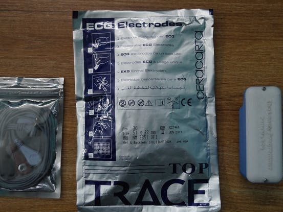
We can go for 3 leads or 4 leads ECG electrodes. This ECG2 click uses both 3 leads measurement methods (LA, LL, RA) and 4 leads measurement (screw terminals are used). The ECG/EKG Cable is connected to the Click board at its 3.5mm earphone jack.
Microchip's AVR-IoT WG Board
This board has an inbuilt temperature sensor and a light sensor that preloaded firmware that publishes the data from the sensors to the cloud. The AVR-IoT WG development board features two sensors:
- A light sensor
- A high-accuracy temperature sensor - MCP9808
- Go from out-of-the-box to cloud-connected in 30 seconds
- Onboard 8-bit MCU brings the processing power and simplicity of the AVR architecture with Core Independent Peripherals (CIPs) which further decrease power consumption
- Secure authentication with hardware-based private key storage
Features:
- ATmega4808 microcontroller
- TEMT6000 Light sensor
- MCP9808 Temperature sensor
- ATECC608A CryptoAuthentication™ device
- WINC1510 WiFi Module
- On-board nEDBG Debugger
- USB and battery-powered
- Integrated Li-Ion/LiPo battery charger
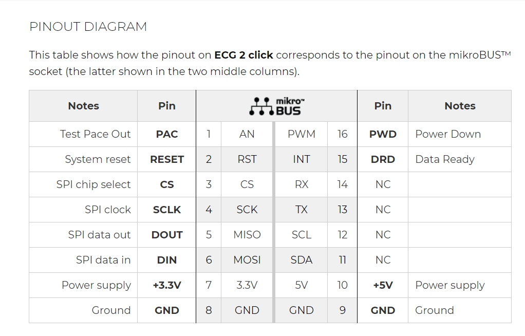
The Circuitry is very simple. We solder the female berg strip to the AVR-IoT WG Development Board and simply plug the ECG2 click board to the AVR-IoT-WG dev board.
We add a Lithium-ion battery to the circuit to make it portable.
For 3 wire measurement, a 3.5mm jack is used.
You can connect the click to a person using three electrodes placed on the left arm, right arm, and the left side of the abdomen (below the heart) or alternatively on the left leg.
We offer cables and electrodes that are marked (left leg (LL) – red, left arm (LA) – black, right arm (RA) – white).
First, log in to the Google IoT core and create a new project and note your Project ID which will be needed later, when you program the hardware to connect to the project.
Note: Here I had used a free trial account. Complete your billing procedure to enable the API.
In the Google Cloud console, you can find the IoT core at the sidebar.
Create a registry:
To Register the device:
Note the Device ID from the Click me file, which will direct you to a link.
In the next form, Fill up device ID with an alphabet at first, the Public key format is of ES256 which can be verified, and add the PUBKEY.txt file in the add device page.
Now the device is successfully added to the Google Cloud.
Programming the AVR-IoT-WG Dev BoardSetup your MPLAB X development environment, create a new project, and open your MCC config file if you have closed it.
For AVR-IoT-WG Compiler, download eitherMPLAB XC8 v2.05 or the AVR GCC Toolchainv3.62.
To install the compiler, open the MPLAB X IDE v5.15, Click Tools -> Plugins
In the MPLAB X IDE Plugins window, click the 'Available Plugins' tab
Select 'MPLAB Code Configurator' and click 'Install' and make sure that it is updated to the recent version of the compiler.
Install MCC libraries
- Open MPLAB X and create an empty project only to open MCC
Before uploading the firmware, we have to create a bus to connect Arduino with the Microchip AVR-IOT-WG Board.
Once the connection is done upload the code for sensors using Arduino IDE.
The code is added to the GitHub Repository which can be found in the code section.
In the case of Microchip, export the project from ATMEL start.
Select the solution configuration as release and debugger as UDPI as nEDBG.
Finally, press the green arrow next to the solution configuration to start the program.
Note: Make sure that the program is properly uploaded without errors, i.e. you'll find the writing process in the output dialog.
Step 5: Setting Up the Google Cloud for Publish and SubscribeCreate a new function in the Google Cloud Functions.
Set the following parameters:
- Trigger - Cloud Pub/Sub
- Topic - AVR-IoT
It automatically generates the code for PUB/SUB functions.
Step 6: 3D-Printed Enclosure- I had made a 3D-printed enclosure for this project.
The necessary files for printing the enclosure is in the Repository. Do try and make one for yourself
- Now Insert the device inside the enclosure and I would look something like this
- We had made the clip like structure that can be attached to a belt.
You can find the data is being published on the Google Cloud.This data which is logged can be display on either a website or with a mobile application.
void main() {

    uint16_t i = 0;
    char final_string[20];
    char time_string[20];
    double time_value = 0.0;
    UART0_Init(57600);
    delay_ms(300);

    GPIO_Digital_Input(&GPIO_PORTH, _GPIO_PINMASK_0);  // pin DRDY is input
    GPIO_Digital_Output(&GPIO_PORTC, _GPIO_PINMASK_4); // pin PWDN is output
    ECG2_PWDN = 1;                                     // ECG2 is powered up
    GPIO_Digital_Output(&GPIO_PORTG, _GPIO_PINMASK_0); // pin CS is output
    ECG2_CS = 1;                                       // deselect ECG2 click
    GPIO_Digital_Output(&GPIO_PORTE, _GPIO_PINMASK_2); // pin RESET is output
    ECG2_RESET = 1;              // pull RESET bit low for 18 CLK to RESET ECG device

    // init SPI
    SPI0_Init_Advanced(500000, _SPI_MASTER, _SPI_8_BIT | _SPI_CLK_IDLE_LOW | _SPI_SECOND_CLK_EDGE_TRANSITION, &_GPIO_MODULE_SPI0_A245);
    ecg2_hal_init();

    // issue RESET pulse
    ECG2_RESET = 0;
    Delay_us(100);
    ECG2_RESET = 1;

    Delay_ms(1000);

    // device is in RDATAC mode, set it to SDATAC mode to edit registers
    ecg2_hal_send_command(SDATAC_COMMAND);
    delay_ms(1000);
    setup_ecg2();

    while (1)
    {
      while (ECG2_DRDY) {} // Wait for ADS1194 device to prepare output data. Data is ready every 8 milliseconds
      Delay_us(5);
      for (i = 0; i < num_bytes_sample; i++)
          ecg_data_sample[i] = SPI_Read(0);   // read ADS1194 output data, one sample

      time_value += 8.0;     // increment time value
      // calculate input voltage
      // voltage LA RA
      channel1_voltage = calculate_ecg_channel( ecg_data_sample, 3, Vref, channel_gain, channel1_voltage_offset );
      // voltage LL RA - channel 2 is usually used for simple ECG
      channel2_voltage = calculate_ecg_channel( ecg_data_sample, 5, Vref, channel_gain, channel2_voltage_offset );
      sprintf(final_string, "%.2f", channel2_voltage); // convert values to string and send to MikroPlot
      strcat(final_string, ",");
      sprintf(time_string, "%.2f", time_value);
      strcat(final_string, time_string);
      Uart_Write_Text(final_string);
      Uart_Write_Text("rn");

      // voltage LL LA
      channel3_voltage = calculate_ecg_channel( ecg_data_sample, 7, vref, channel_gain, channel3_voltage_offset );
      // voltage from temperature sensor
      channel4_voltage = calculate_ecg_channel( ecg_data_sample, 9, vref, channel_gain, channel4_voltage_offset );
    }
  }
if you faced any issues in building this project, feel free to ask me. Please do suggest new projects that you want me to do next.
DISCLAIMER: ECG 2 click is a prototyping tool, not a medical-grade device. Do not use it to diagnose patients.
Give a thumbs up if it really helped you and do follow my channel for interesting projects. :)
Share this video if you like.
Happy to have you subscribed: https://www.youtube.com/c/rahulkhanna24june?sub_confirmation=1
Thanks for reading!


Comments