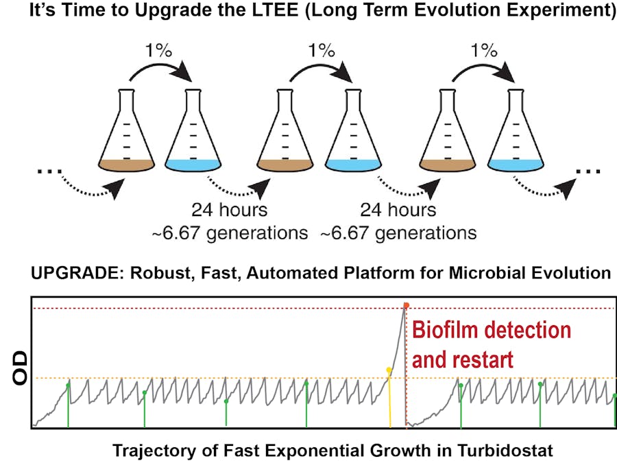
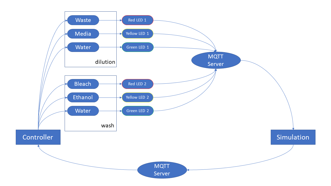
We are building an array of robust turbidostat system that will enable us to run multiple microbial evolution runs in parallel to check impacts of different conditions, or repeatability of certain trajectories. We spent a month designing the controller system to ensure its robustness with respect to internal fluctuations (e.g. growth fluctuations and mutations) and external fluctuations (media, temperature, dilution etc.) and with respect to catastrophic events like media contamination and biofilm formation. Our final version of the controller implemented in a raspberry Pi enables us to maintain robust dilution cycles in presence of the above mentioned disturbances. First, we tested its performance by running simulated growth-trajectories with noisy growth-rate and low-probability catastrophic events and then on real engineered hardware, and now it is successfully running multi-day long evolution experiments.
The Turbidostat:
The basic principle of a turbidostat is to keep the turbidity of the liquid culture in a quasi-constant mode, by diluting the culture every time it reaches certain turbidity threshold. The main module of a turbidostat therefore is the growth-chamber where the liquid culture is grown. The turbidity, often termed optical density of the culture, is monitored using the scattering or transmission of a beam across the culture. The signal is monitored and when it reaches a certain threshold, some of the original culture is removed and is replaced with clear fresh growth-medium, which reduces the turbidity. Therefore the basic controller to run a turbidostat in automated fashion needs to record and monitor the optical density of the culture continuously (with high time resolution) and send signals to pumps and valves to remove culture and add media. However, if we plan to use the turbidostat for long-term evolution experiments, we need to address a few additional problems.
First, for a such a long experiment, the amount of media required to dilute the culture over time is quite large. For a culture-volume of 10 ml, we need to add 5 ml dilution media every doubling time. So, if we are using a fast growth-condition (which is the goal here, to get large rounds of doubling events in short time) that enables 20 min doubling time, we need 360 mL media per day, 2.5 L media per week, 10 L per month, and 120 L per year. For a 8 replicate system, this become 1,000 L growth-media per year. Storing such large volume of rich growth-media is problematic for several reasons. So, we have designed an inline automated media prep system that addresses these issues. We discuss them in detail in the respective section ( Section 2). Secondly, often during the evolution experiments cells form biofilms and since that enables them to preferentially stick around through the dilution process, it gets easily selected upon. Also, when the biofilm formation becomes severe, it clogs the system and interferes with the measurement system. Therefore, we have designed a system that can detect such events early enough and can clean and restart the run from the previous timepoint. Lastly, to monitor the progression of the evolution in the culture, we want to design and engineer an automated fossil record collection system, that collects a small aliquot of the liquid culture in regular time interval and stores them in a 1084-well array that is kept in 4 deg C, to avoid further growth. We are in the process of finishing this setup, but are also considering a second setup where the culture is stored in a continuous time-line, enabling us to get a much more detailed look at the trajectories.
1. Growth-Chamber:
To minimize the amount of media components and other reagents required for such long-term experiment (current goal is 1 year long run) with multiple replicates (current goal is to have 8-16 replicates), we decided to use a mini-culture setup (10 ml volume). We custom engineered the growth-chamber using commercial glass vials and PEEK tubings. The culture in the vial is continuously stirred in between the measurements using a magnitic stir-bar that is controlled by a circular magnet attached to fan below the chamber. We have designed an optimized a 3D printed housing for the chamber and the LEDs that monitor of optical density of the culture inside. The details of the design and construction are given below.
1A. Design and construction of the chamber:
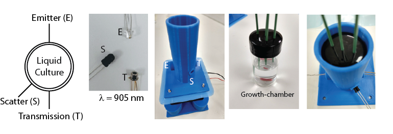
The chamber is constructed using a glass vial. We drilled holes in the cap to insert PEEK tubings (inert material for different chemicals and detergents to be used). There is one main inlet which brings new media in, and an outlet which takes out the culture to waste or for fossil record collection. There are two additional inlets for bringing in any stressor solution to examine its impact on evolution, and to bring in cleaning solutions if biofilms are detected. The liquid culture in this growth-chamber is stirred with a magnetic stirrer bar. The bar is controlled using a circular magnet attached to a fan which is mounted below the chamber, and whose speed and on/off state is being controlled from the central controller.
1B. OD measurements:
The controller monitors the optical density of the growing culture and sends dilution signals to the peristaltic pumps. In order to monitor the optical density, we have designed a housing for the growth-chamber that enables to measure both the scattering (120 deg) and transmission (180 deg) of a beam passed through the culture. The transmission signal is more sensitive in the low OD regime, whereas the scattering is more sensitive in the high OD regime. A combination of this signals is used to robustly estimate the optical density of the culture at any part of the growth-curve. We use IR beams at 905 nm, as we measured and validated that the absorption from the media components in this wavelength is minimal. This will be also helpful to monitor growth of cells carrying fluorescent reporters, without worrying about the expression level of fluorescent proteins from the cells complicating the results.
1C. Chamber Installation:
The chamber is installed in a housing that holds the LEDs (emitters and sensors) as well. The bottom part of the assembly houses the fan on top of which the circular magnet is installed. The bottom part can be printed for multiple turbidostat in one platform, or for individual ones. First, the fan is installed on the bottom piece and then the circular magnet is attached to the fan using a double-sided tape. The top part, which is the housing for the chamber and LEDs, is then installed on top of the fan. The distance between the fan and the bottom of the housing is optimized to make sure the the magnetic stir-bar in the growth-chamber can be properly controlled by the circular magnet. The speed and on/off state of the magnet is controlled from the central controller. The height of the housing is optimized in a way that once the growth-chamber is put inside the housing, no ambient light gets in the chamber, which is crucial for the transmission and scattering measurements. The entire assembly is kept in an incubator (custom-designed) that controls the temperature and humidity.
1D. Measurements:
The frequency of data collection is a user-defined variable. For the results presented here, we collected data every 30 seconds. In every round, the fan is stopped 3 seconds before the measurement starts. This allows the stir-bar to settle down and avoids the noise from the culture being stirred. Then the LED is turned on (red) and the transmission is recorded (black). Then the fan is turned on, which rotates the circular magnet that keeps the culture stirred, and is kept on for 24 secs. We record the data only when the LED is turned on and then take the average of all the measurements during that window to get a smooth transmission value, which is then log-transformed according to the calibration to get the OD value of the culture.
Below are transmission-OD plots from example traces of turbidostat run (upto 17 hours). The user can set the OD value at which the culture is to be kept and can be reached from both direction (OD target - 0.3, top-left --low to high, top-right-- high to low). We can also select different dilution periods and volumes (bottom-left --2%, bottom-right -- 20%).
2. Automated Inline Media Prep:
As mentioned earlier, even with our mini-culture setup, the volume of media required to dilute the system over time, for even a month is quite large (10L/month for a single turbidostat, and 80L/month for a 8-replicate system). Storing such large volume of media is problematic for several reasons. First of all, to keep such large volume media, we need large containers that are cumbersome and also prevent them from being contaminated, since such reach media is prone to get contaminated quite frequently. One option is to store such large volume in 4 deg C, which avoids contamination, but is still quite problematic, as we need to quickly warm it up during the dilution process, to avoid cold-shocking the cells in our culture. Our solution is to keep the media stored in 20x concentration and then dilute it in-line in a secondary chamber, with a water source. The 20x media requires much less volume and is also much less susceptible to contamination, due to its very high osmolarity. The water can be collected from a distilled water container/drum. They are then mixed in a secondary chamber which has a transmission signal recorder to report when the components are well mixed and ready, and a level-sensor to bring more components when the media is running low. The 20x media and the water are brought to the container using a pair of high-speed peristaltic pump and stirred using a magnetic stirrer. The transmission signal becomes steady once the components are well mixed and reports the ready-status.
3. Automated Cleaning System:
In order to remove the biofilm or any unwanted contamination, we have designed an automated clean-up system that sequentially delivers bleach, ethanol, and water to the growth-chamber or the media prep chamber. The design and final version of the setup is given below. The high-speed pump and the solenoid pinch valves are controlled by a dedicated raspberry pi that integrates this setup with the central controller.
4. Automated Fossil Record Collection:
This is part we are currently mostly pushing for. More details soon.
5. The complete setup and outlook:
We are working towards making the controller more robust and collecting high-res data for growth, fitness, and sequences over time.


Comments
Please log in or sign up to comment.