


Hardware components | ||||||
| × | 1 | ||||
| × | 1 | ||||
Software apps and online services | ||||||
 |
| |||||
So you got your new robot project and you have selected DC motors as its propulsion. But how do you control them? A gnarly home made perf board motor control driver? No...... You wouldn't want to mess up your pretty robot with all the jagged wires now would you? Don't worry that's why the engineers at Aptinex have designed Dagaya for you.
FeaturesCompact PCB Size: 60 mm x 58 mm
Small enough to easily integrate into your robot without taking up too much space.
Wide Operating Voltage: 5.5V – 24V
Dagaya 2.0 supports a broad voltage range, making it adaptable to various power supplies.
High Current Capacity:
Continuous Output: Up to 12A per channel
Maximum Output: 30A per channel
For even more power, you can combine outputs to deliver up to 24A continuous (60A maximum) to a single motor. Perfect for powering demanding DC motors.
Versatile Input Compatibility:
Supports both 5V and 3.3V inputs, making it compatible with most microcontrollers. The logic high threshold is 2.1V.
PWM Operation:
With a frequency of up to 20 kHz, it ensures smooth motor control even at high speeds.
Current Sensing:
The current sense voltage output is approximately 140 mV/A, giving you precise motor current monitoring.
Universal Compatibility:
Dagaya 2.0 can be used with almost any microcontroller, including Arduino, Raspberry Pi, PIC microcontrollers, and others.
Robust Protection Features:
Reverse-Voltage Protection: Can handle reverse voltages down to -16V.
Input Voltage Range: Survives input voltages up to 41V.
Undervoltage and Overvoltage Shutdown: Protects your motor and driver from unstable power conditions.
Thermal Shutdown: High-side and low-side thermal shutdown to prevent overheating.
Short Protection: Short-to-ground and short-to-Vcc protection to ensure safe operation.
Cross-Conduction Protection: Prevents both sides of the motor driver from being on simultaneously.
Charge Pump Output: Provides reverse polarity protection to safeguard your system.
Applications- Industrial Automation
- Robotics
- Home Automation
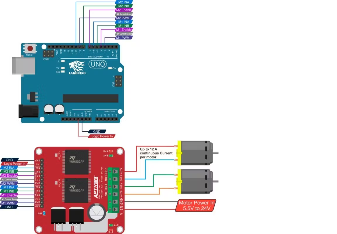
EN - Bridge Enable input. When the EN pin is in logic low motor enters the brake mode.
PWM – Pulse width modulation. Controls the speed of the motor.
INA - Control the direction of the motor. Drive in the forward direction.
INA - Control the direction of the motor. Drive in the reverse direction.
CS – Measure the current drawn by the motor.
GND- Connects to Ground.
Pin connections- Connect DAGAYA Pulse Duo Motor Driver with Microcontroller as follows.
- Upload the code to the microcontroller.
This Arduino code is designed to control two DC motors using a motor driver. It uses Pulse Width Modulation (PWM) to adjust the speed of the motors and digital signals to control their direction. There are two demo functions—demoOne() and demoTwo()—that run the motors in different ways.
1. Pin Assignments:
// connect motor controller pins to Arduino digital pins
// motor one
int enA = 10;
int in1 = 9;
int in2 = 8;

// motor two
int enB = 5;
int in3 = 7;
int in4 = 6;- enA and enB: These pins are used to control the speed of Motor A and Motor B through PWM.
- in1 and in2: Control the direction of Motor A.
- in3 and in4: Control the direction of Motor B.
2. setup() function:
void setup()
{
// set all the motor control pins to outputs
pinMode(enA, OUTPUT);
pinMode(enB, OUTPUT);
pinMode(in1, OUTPUT);
pinMode(in2, OUTPUT);
pinMode(in3, OUTPUT);
pinMode(in4, OUTPUT);
}- The pinMode function sets all the control pins for both motors as OUTPUT to control the motor driver.
- Motor A is controlled by in1, in2, and enA.
- Motor B is controlled by in3, in4, and enB.
3.demoOne() function:
void demoOne()
{
// this function will run the motors in both directions at a fixed speed
// turn on motor A
digitalWrite(in1, HIGH);
digitalWrite(in2, LOW);
// set speed to 200 out of possible range 0~255
analogWrite(enA, 200);
// turn on motor B
digitalWrite(in3, HIGH);
digitalWrite(in4, LOW);
// set speed to 200 out of possible range 0~255
analogWrite(enB, 200);
delay(2000);
// now change motor directions
digitalWrite(in1, LOW);
digitalWrite(in2, HIGH);
digitalWrite(in3, LOW);
digitalWrite(in4, HIGH);
delay(2000);
// now turn off motors
digitalWrite(in1, LOW);
digitalWrite(in2, LOW);
digitalWrite(in3, LOW);
digitalWrite(in4, LOW);
}
Motor A:
- First, it's set to spin forward by setting in1 high and in2 low.
- The speed is set to 200 using
analogWrite(enA, 200), which is PWM control where the maximum speed is 255.
Motor B:
- It follows the same control logic as Motor A (spin forward with a speed of 200).
- After 2 seconds, both motors are set to reverse by swapping the control signals (in1 low, in2 high for Motor A, and in3 low, in4 high for Motor B).
- After 2 more seconds, the motors are stopped by setting all control signals to LOW.
4. demoTwo() function:
void demoTwo()
{
// this function will run the motors across the range of possible speeds
// note that maximum speed is determined by the motor itself and the operating voltage
// the PWM values sent by analogWrite() are fractions of the maximum speed possible
// by your hardware
// turn on motors
digitalWrite(in1, LOW);
digitalWrite(in2, HIGH);
digitalWrite(in3, LOW);
digitalWrite(in4, HIGH);
// accelerate from zero to maximum speed
for (int i = 0; i < 256; i++)
{
analogWrite(enA, i);
analogWrite(enB, i);
delay(20);
}
// decelerate from maximum speed to zero
for (int i = 255; i >= 0; --i)
{
analogWrite(enA, i);
analogWrite(enB, i);
delay(20);
}
// now turn off motors
digitalWrite(in1, LOW);
digitalWrite(in2, LOW);
digitalWrite(in3, LOW);
digitalWrite(in4, LOW);
}- In this function, both motors are set to spin in reverse (Motor A: in1 low, in2 high; Motor B: in3 low, in4 high).
- The speed of both motors is gradually increased from 0 to the maximum (255) using a for-loop that increments the PWM value every 20 milliseconds.
- Once the maximum speed is reached, the motors then decelerate back to zero, again using a for-loop.
- After the speed returns to zero, both motors are turned off.
5. loop() function:
void loop()
{
demoOne();
delay(1000);
demoTwo();
delay(1000);
}- The loop() function alternates between running
demoOne()anddemoTwo()with a 1-second delay between each. demoOne()runs first, where the motors change direction after running at a fixed speed.demoTwo()follows, where the motors accelerate and decelerate across the full speed range.
It's alive! Now use this in whatever that requires DC motors!
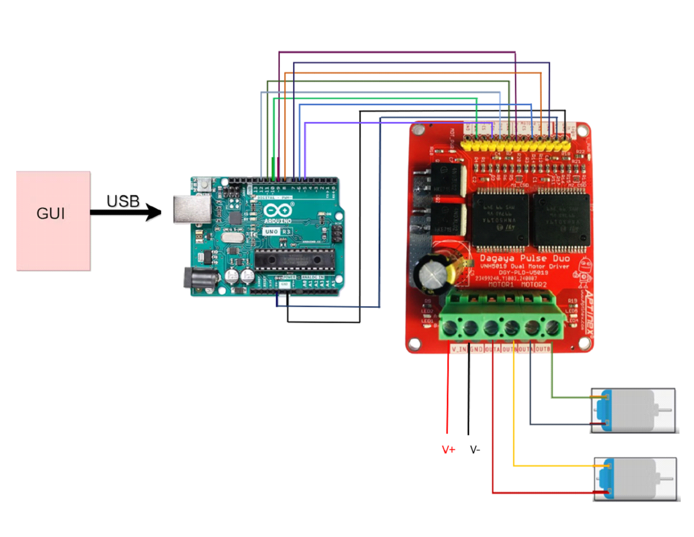
Now let's build up an Arduino code and a GUI using python to control the motors according to user commands.Arduino code for accept user given commands.
Step 1 :
- Upload the below code to Arduino Board.
/ Pin assignments
const int motorAPin = 9;    // PWM pin for Motor A (motor 2)
const int motorBPin = 10;   // PWM pin for Motor B (motor 1)
const int dirAPin = 7;      // Forward direction pin for Motor A
const int revAPin = 8;      // Reverse direction pin for Motor A
const int dirBPin = 11;     // Forward direction pin for Motor B
const int revBPin = 12;    // Reverse direction pin for Motor B
//const int brakePinA = 6;    // Brake pin for Motor A
//const int brakePinB = 5;    // Brake pin for Motor B
int speed=0;


void setup() {
  pinMode(motorAPin, OUTPUT);
  pinMode(motorBPin, OUTPUT);
  pinMode(dirAPin, OUTPUT);
  pinMode(revAPin, OUTPUT);
  pinMode(dirBPin, OUTPUT);
  pinMode(revBPin, OUTPUT);
  pinMode(6, OUTPUT); //pinMode(brakePinA, OUTPUT);
  pinMode(5, OUTPUT); //pinMode(brakePinB, OUTPUT);


  Serial.begin(9600);
  Serial.println("Enter commands to control motors:");
}

void loop() {
  if (Serial.available() > 0) {
    String command = Serial.readStringUntil('\n');
    command.trim();
    command.toUpperCase(); // Ensure command is in uppercase

    if (command == "AON") {
      digitalWrite(motorAPin, HIGH); // Max speed
      //digitalWrite(brakePinA, LOW); // Release brake
      Serial.println("Motor A ON");
    }
    else if (command == "AOFF") {

      digitalWrite(motorAPin, LOW); // Stop motor
      Serial.println("Motor A OFF");
    }
    else if (command == "ADIRFWD") {
       digitalWrite(motorAPin, HIGH);
      digitalWrite(dirAPin, HIGH); // Set direction to forward
      digitalWrite(revAPin, LOW);
       analogWrite(motorAPin, speed);
      Serial.println("Motor A Forward");
    }
    else if (command == "ADIRREV") {
       digitalWrite(motorAPin, HIGH);
      digitalWrite(revAPin, HIGH); // Set direction to reverse
      digitalWrite(dirAPin, LOW);
       analogWrite(motorAPin, speed);
      Serial.println("Motor A Reverse");
    }
    /*else if (command == "ABRAKE") {
      digitalWrite(brakePinA, HIGH); // Engage brake
      Serial.println("Motor A Brake");
    }*/
    else if (command.startsWith("ASPEED")) {
       speed = command.substring(6).toInt();
      speed = constrain(speed, 0, 255); // Ensure speed is within 0-255
      analogWrite(motorAPin, speed);
      Serial.println("Motor A Speed: " + String(speed));
    }

    // Similar controls for Motor B
    else if (command == "BON") {
      digitalWrite(motorBPin, HIGH);
      //digitalWrite(brakePinB, LOW);
      Serial.println("Motor B ON");
    }
    else if (command == "BOFF") {
      digitalWrite(motorBPin, LOW);
      Serial.println("Motor B OFF");
    }
    else if (command == "BDIRFWD") {
      digitalWrite(motorBPin, HIGH);
      digitalWrite(dirBPin, HIGH);
      digitalWrite(revBPin, LOW);
      analogWrite(motorBPin, speed);
      Serial.println("Motor B Forward");
    }
    else if (command == "BDIRREV") {
      digitalWrite(motorBPin, HIGH);
      digitalWrite(revBPin, HIGH);
      digitalWrite(dirBPin, LOW);
      analogWrite(motorBPin, speed);
      Serial.println("Motor B Reverse");
    }
    /*else if (command == "BBRAKE") {
      digitalWrite(brakePinB, HIGH);
      Serial.println("Motor B Brake");
    }*/
    else if (command.startsWith("BSPEED")) {
      int speed = command.substring(6).toInt();
      speed = constrain(speed, 0, 255); // Ensure speed is within 0-255
      analogWrite(motorBPin, speed);
      Serial.println("Motor B Speed: " + String(speed));
    }
    else {
      Serial.println("Invalid Command");
    }
  }
}
Step 2 :
- Open the serial monitor and enter commands.
Building a GUI application on windows to send commands.
To create a graphical user interface (GUI) that sends commands to the Arduino, we can use Python with the Tkinter library for the GUI and the PySerial library for serial communication.
Step 1 :
- Install Python.
Step 2 :
- Install PySerial.
If you are using Python Software;
Open the Command Prompt and run:
pip install pyserial
If you are using Thonny;
Open Thonny IDE >> Tools >> Manage Packages >> Search Pyserial on search bar >> Select Pyserial and click install.
Step 3 :
- Write the Python GUI Application.
Here's a simple Python script that creates a GUI with buttons and sliders to control Motor A and Motor B.
import tkinter as tk
from tkinter import messagebox
import serial
import threading
import time

SERIAL_PORT = 'COM3'
BAUD_RATE = 9600
ser = serial.Serial(SERIAL_PORT, BAUD_RATE, timeout=1)
def send_command(command):
    ser.write((command + '\n').encode())

def motor_a_on():
    send_command('AON')

def motor_a_off():
    send_command('AOFF')

def motor_a_dir_fwd():
    send_command('ADIRFWD')

def motor_a_dir_rev():
    send_command('ADIRREV')

#def motor_a_brake():
    #send_command('ABRAKE')

def motor_a_speed(val):
    send_command(f'ASPEED{int(float(val))}')

def motor_b_on():
    send_command('BON')

def motor_b_off():
    send_command('BOFF')

def motor_b_dir_fwd():
    send_command('BDIRFWD')

def motor_b_dir_rev():
    send_command('BDIRREV')

#def motor_b_brake():
    #send_command('BBRAKE')

def motor_b_speed(val):
    send_command(f'BSPEED{int(float(val))}')

def read_serial():
    while True:
        if ser.in_waiting:
            line = ser.readline().decode().strip()
            if line:
                print(f"Arduino: {line}")

# Start a thread to read serial data
threading.Thread(target=read_serial, daemon=True).start()

# Build the GUI
root = tk.Tk()
root.title("Motor Control GUI")

# Motor A Controls
motor_a_frame = tk.LabelFrame(root, text="Motor A Controls", padx=10, pady=10)
motor_a_frame.grid(row=0, column=0, padx=10, pady=10)

tk.Button(motor_a_frame, text="ON", width=10, command=motor_a_on).grid(row=0, column=0, pady=5)
tk.Button(motor_a_frame, text="OFF", width=10, command=motor_a_off).grid(row=0, column=1, pady=5)
tk.Button(motor_a_frame, text="Forward", width=10, command=motor_a_dir_fwd).grid(row=1, column=0, pady=5)
tk.Button(motor_a_frame, text="Reverse", width=10, command=motor_a_dir_rev).grid(row=1, column=1, pady=5)
#tk.Button(motor_a_frame, text="Brake", width=10, command=motor_a_brake).grid(row=2, column=0, columnspan=2, pady=5)
tk.Label(motor_a_frame, text="Speed").grid(row=3, column=0, columnspan=2)
motor_a_speed_slider = tk.Scale(motor_a_frame, from_=0, to=255, orient=tk.HORIZONTAL, command=motor_a_speed)
motor_a_speed_slider.set(255)
motor_a_speed_slider.grid(row=4, column=0, columnspan=2, pady=5)

# Motor B Controls
motor_b_frame = tk.LabelFrame(root, text="Motor B Controls", padx=10, pady=10)
motor_b_frame.grid(row=0, column=1, padx=10, pady=10)

tk.Button(motor_b_frame, text="ON", width=10, command=motor_b_on).grid(row=0, column=0, pady=5)
tk.Button(motor_b_frame, text="OFF", width=10, command=motor_b_off).grid(row=0, column=1, pady=5)
tk.Button(motor_b_frame, text="Forward", width=10, command=motor_b_dir_fwd).grid(row=1, column=0, pady=5)
tk.Button(motor_b_frame, text="Reverse", width=10, command=motor_b_dir_rev).grid(row=1, column=1, pady=5)
#tk.Button(motor_b_frame, text="Brake", width=10, command=motor_b_brake).grid(row=2, column=0, columnspan=2, pady=5)
tk.Label(motor_b_frame, text="Speed").grid(row=3, column=0, columnspan=2)
motor_b_speed_slider = tk.Scale(motor_b_frame, from_=0, to=255, orient=tk.HORIZONTAL, command=motor_b_speed)
motor_b_speed_slider.set(255)
motor_b_speed_slider.grid(row=4, column=0, columnspan=2, pady=5)

root.mainloop()
Step 4 :
- Run the code. You can see the GUI application with buttons and slider. You can click the buttons to On and off the motors and change the direction of two motors and slider to change speed of motors.
Key Points of the GUI Application.
1. Serial Communication.
- The script attempts to open a serial connection to the Arduino on the specified `SERIAL_PORT` at the defined `BAUD_RATE`.
- A separate thread continuously reads data from the Arduino and prints it to the console.
2. GUI Elements.
- The GUI has two sections: one for Motor A and another for Motor B.
- Each section contains buttons to turn the motor ON/OFF, set direction (Forward/Reverse), apply Brake, and a slider to adjust the speed.
3. Command Sending.
- Clicking a button or adjusting the slider sends the corresponding command to the Arduino over the serial connection.
4. Usage.
- Ensure the Arduino is connected to the specified `COM` port.
- Run the Python script. A window will appear with controls for both motors.
- Use the buttons and sliders to control the motors interactively.
Note:- Replace "COM3" in the `SERIAL_PORT` variable with the actual COM port your Arduino is connected to. You can find this in the Arduino IDE under Tools > Port.


Comments
Please log in or sign up to comment.