


Hardware components | ||||||
 |
| × | 1 | |||
| × | 1 | ||||
Software apps and online services | ||||||
 |
| |||||
| ||||||
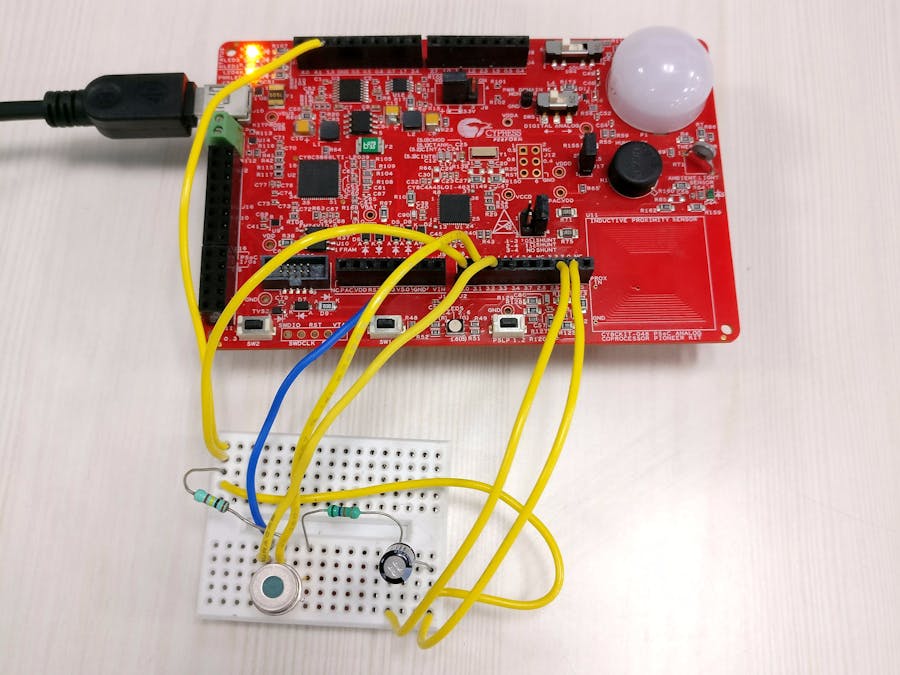
This project shows the design to implement non-contact temperature measurement solution in PSoC Analog Coprocessor device.
TE Sensor Solution’s TS305-11C55 thermopile sensor is used which has a measurement range of 0°C to 100°C. The datasheet gives a graph showing the relation between the object temperature and the thermopile generated voltage.
As seen from the above graph, voltage approximately varies between -1.5mV to 7mV over the object temperature of 0°C to 100°C. This will require some amplification before giving it to the analog to digital converter. Also, as the generated voltage can be negative, a bias voltage is required.
Similar to thermocouple applications, thermopile also requires ambient temperature compensation. TS305-11C55 houses a thermistor for this purpose. The design presented here targets to achieve sensitivity of approximately 0.2°C.
PSoC Creator designPSoC Creator design is shown below.
Thermopile sensor output is a DC signal with a high output impedance, making it susceptible to noise. An RC filter with very low cut-off frequency (our information is DC anyways) eliminates most of the noise. The sensor is biased using 1.2V buffered 1.2V band-gap reference voltage. The filtered signal is amplified using a differential amplifier created using two programmable gain amplifiers (PGAs). The gain for this application is set to maximum of 32 to achieve the required sensitivity. The differential output of the amplifier is measured using 12-bit SAR ADC. The AMUX component is used to create a chopping (+/- 1 gain) infrastructure to eliminate the effects of PGA and ADC offset.
For the ambient temperature compensation, a reference resistor of 100KΩ (equal to the nominal value of thermistor) is connected in series to the thermistor. This potential divider is biased using 1.2V reference voltage. The voltages across the reference resistor and the thermistor is measured using 12-bit SAR ADC.
As shown in the thermopile output characteristics, there is a non-linear relationship between the object temperature and the generated voltage. There are two ways to derive the temperature value based on the ADC readings. One approach is to write an equation describing the relation between object temperature and the thermopile output. Another approach is to break the curve into many linear segments and use one of many linear equations. The second approach involves less math, and thus avoids complex math libraries and memory space. The second approach is taken for this design. A ten point look up table (LUT) is created referring the thermopile output characteristics.
The computation of the object temperatureThe computation of the object temperature involves following steps:
1. Measuring the ambient temperature using thermistor
2. Calculating the equivalent thermopile voltage at the measured ambient temperature
3. Measuring the thermopile output voltage
4. Adding the compensation voltage (measured in step 2) to the thermopile voltage.
5. Calculating the object temperature
The design uses a timer to generate interrupt every 1ms. Measurements are taken on every timer interrupt. I2C is used to communicate measured ADC counts for thermopile voltage, reference resistor voltage and the thermistor voltage, and the calculated thermistor resistance, ambient temperature and the object temperature.
Modifications to the CY8CKIT-048 PSoC Analog Coprocessor Pioneer Kit- Remove R131 and R161 as they are connected to the sensors on the board
- Solder a 1uF capacitor at C43 (required as the ADC bypass cap)
Cypress Bridge Control Panel software is used to test the project. The software displays the data received over I2C lines.
The following reading shows the object temperature curve in blue (in °C with 10x scaling) and the thermopile ADC counts in black, when the palm is kept over the sensor (ensuring the viewing angle of the sensor is completely covered).
Other data – reference resistor voltage counts, thermistor voltage counts, thermistor resistance and the ambient temperature can also be observed.
For ease of testing, Bridge Control Panel’s iic (for data receive command) and ini (for variable declaration) files are also attached.
1. Temperature measurement sensitivity can be improved by adding another amplifier stage. PSoC Analog Coprocessor has one Opamp still free!
2. While testing, ensure the viewing angle of the sensor is completely covered by the object whose temperature is to be measured. The viewing angle characteristics is given in the sensor datasheet.
3. The infrared emissivity depends on the object. Check this: http://www.raytek.com/Raytek/en-r0/IREducation/EmissivityNonMetals.htm


Comments
Please log in or sign up to comment.