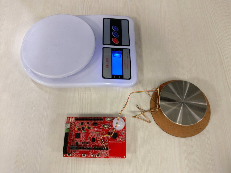
This project describes the making of a simple weighing scale using the Cypress PSoC Analog Coprocessor and a weight/load sensor (also known as a load cell or strain gauge).
DetailsA Load cell is a transducer which converts the applied force into change in resistance. The fundamental principle behind the working is the Poisson effect. The application of force on a material in one direction, leads to a deformation in the perpendicular direction. Resistances of the load cell are arranged in the form of a Wheatstone bridge. The goal is to measure this change in resistance and translate it back into the units of force (or weight).
For this project, the load cell used is a TE FX1901-0001-0025L with the full scale input force of 25 lbf (11.34 kg) and the output voltage span of 20mV/V. This means that if we power the load cell with a voltage (a.k.a "excitation voltage") of 5.0V (typical PSoC VDD), the output span would be 100mV. The TE load cell encompasses a circuit similar to the Wheatstone bridge with one of the arms being the strain gauge which is sensitive to force. The load cell exposes two terminals at which the excitation voltage is to be provided, and two other terminals for the output. The differential voltage across the output is sensed using an analog front end (AFE) implemented in the PSoC Analog Coprocessor. The sensed values are translated into the corresponding mass and made accessible through an I2C interface. The project is implemented on a PSoC Analog Coprocessor kit (CY8CKIT-048) which can be connected to the PC and the output can be visualized on Bridge Control Panel software (the related configuration files LoadCell_BCP.iic and LoadCell_BCP.ini are attached). The red LED on the kit is also made to glow proportional to the sensed load.
The load cell has a typical output resistance (across the output terminals) of 2.2 kOhm. This signal is amplified using a differential amplifier created using two programmable gain amplifiers (PGAs). The gain for this application is set to 21.3 to achieve the required sensitivity. The differential output of the amplifier is measured using a SAR ADC. In this project we leverage the averaging feature built into the SAR ADC Creator software component to get 16-bits of resolution. The AMUX component is used to create a chopping (+/- 1 gain) infrastructure to eliminate the effects of PGA and ADC offset. You'll notice that a similar AFE is used in the thermopile project.
The PSoC Creator schematic design is shown below.
We were in for a surprise when we realized that we had received only the load cell with no other mechanical components that are needed to make a platform onto which we can load weights. But we are makers and obviously don't let that stop us, right? A piece of plastic came to the rescue (this mysterious plastic thingy is common in Indian households, if you're able to identify this, do post it in the comments) and was used as a support between a metal plate and the compression element of the load cell. Some sawing and hot-gluing later, our scale was ready to carry some load.
Make the following modifications on the PSoC kit:
- Solder a 1uF capacitor at C43 (required as the ADC bypass cap)
- Remove R131 and R161 as they are connected to the sensors on the board
Make the following hardware connections:
- Connect the positive lead of load cell output (yellow wire) to P2.1 on J2 on the kit
- Connect the negative lead of load cell output (white wire) to P2.5 on J2 on the kit
- Connect the red wire to V5.0 on J1 on the kit
- Connect the black wire to GND on J1 on the kit
The firmware consists of initializing the AFE, gathering the data from the ADC, doing some processing and sending the data over an I2C interface.
The output of the AFE is just a bunch of noisy numbers from the ADC and we need to process it to convert it to meaningful weight data. An IIR filter is implemented in firmware to reduce the noise in the ADC values. We then 'calibrate' which is a process of correlating the ADC counts with the actual mass of the object weighed. The method we followed is quite straight forward, but involves use of a 'standard' against which we compare our outputs. In our case this was a kitchen weighing scale, using which we weigh a couple of objects and also note down the counts measured by the ADC (we observe these values by reading them over I2C using Bridge control panel software). Once we have enough data points, we can fit them into a curve and feed this equation back into the firmware. The spreadsheet that we used is attached and can be used as a template. The resultant curve's equation (polynomial) can be entered in the firmware by modifying the coefficients.
/* Equation from spreadsheet */
/* y = 6E-09x3 + 9E-06x2 + 0.1923x - 0.5714 */
/* Enter the co-effficients of the fitted curve from the load cell calibration spreadsheet */
#define MASS_COEFF_ORDER3 (+0.000000006)
#define MASS_COEFF_ORDER2 (+0.000009000)
#define MASS_COEFF_ORDER1 (+0.192300000)
#define MASS_COEFF_ORDER0 (-0.571400000)


Comments
Please log in or sign up to comment.