


Hardware components | ||||||
 |
| × | 2 | |||
 |
| × | 2 | |||
 |
| × | 1 | |||
 |
| × | 1 | |||
 |
| × | 1 | |||
 |
| × | 1 | |||
 |
| × | 1 | |||
 |
| × | 1 | |||
Software apps and online services | ||||||
 |
| |||||
This project was made by Sam Hofmann and George Powell for MEGR 3171 (Instrumentation) at UNC Charlotte with Professor McAlpine. It is a sleep cycle alarm clock that turns on the lights and brews coffee. It is triggered by a motion sensor and controlled by two Particle Photons. It is designed to make your morning feel a little less like morning!
In order to understand the motivation behind this project, a little bit of background knowledge is necessary. This project is made around the desire for a better morning, and what's the worst part about mornings? Waking up. The following is an explanation as to why waking up can be so awful, and why our project makes it better.
When you sleep, your body goes through sleep cycles, fluctuating between light and deep sleep throughout the night. If your alarm clock happens to go off while you are in deep sleep, chances are you will feel drowsy and have a hard time getting out of bed. This is known as sleep inertia. However, if you wake up during light sleep, chances are your morning will be much less dreadful.
During light sleep, it is common to toss and turn in bed. This is convenient because this allows for a way to tell what stage of sleep you are in using a motion sensor. The idea is that you enter a time range during which you wish to be woken up, and the motion sensor runs for that time range, turning on the alarm when it sees movement. There are already apps that exist that do exactly this.
In addition, being exposed to light when you first wake up is thought to help the body transition from being asleep to being awake. So, it would be a nice feature if this alarm could also turn on the lights for us. The idea of a "sunrise alarm clock" is not new, and it is thought by many to be a much more gentle way of waking up. You could say that our project is a combination of a sleep cycle/sunrise alarm clock. On top of that, it makes you coffee! I don't think we need to explain the science behind how coffee can help you wake up.
The Process:Below is a flow diagram of the sequence of events that the system goes through:
In addition to the items listed, a few additional items were necessary to complete this project.
- two three-prong extension cords (to be modified for the relays)
- electrical tape
- mini breadboard(s)
- coffee maker (controlled by relay)
- lights (controlled by relay)
- programmable wall outlet timer (to set your alarm)
- connecting wires (M-F and M-M)
This project deals with high voltages. Please use caution when stripping, splicing, soldering, etc. Just unplug it!
To decide if a relay is safe for use with a certain appliance, check the specs on the relay and the appliance. Power = current*voltage, so if you have a relay that will be switching 120VAC and it has a maximum current of 10A, then you can safely switch a device rated up to 1200W. We used a 5A relay to switch our 140W lights and a 10A relay to switch our 650W coffee maker.
Also, we used two 5VDC adapters (cell phone chargers) to power our Photons from the outlets. If you are planning to go this route, make absolutely sure that the output of the adapter is 5VDC. It must be 5V and it must be DC. You can always use batteries to power the Photon, as well.
Preliminary Tinkering:Before making the circuits and writing the code, we did a little modifying of the extension cords. First, the extension cords were cut open and the insulation was stripped back, exposing three wires (white, green, and black). The black wire was cut open and stripped back to expose the leads, as shown below.
The two exposed leads will be attached to the COM and NO connections on the relay. You can leave the white and green wires intact or you can cut them open and splice or solder them back together.
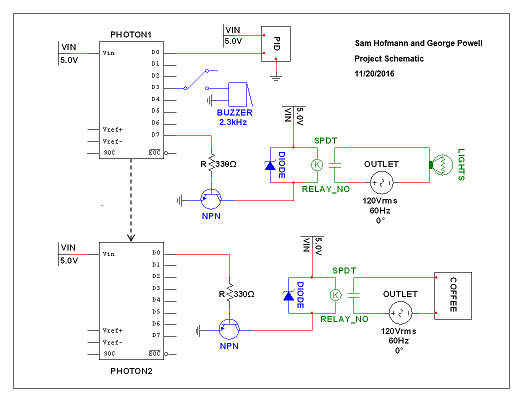
Relay Subcircuit:This part is optional, and is really only recommended if you have a relay laying around that isn't attached to a control board. Below is a schematic of the relay subcircuit. It is also included in the project schematic near the bottom of the page.
This can all be replaced with a relay module. We used an SPDT relay rated at 5V so that it was compatible with the Photon. We used the resistor specified above instead of a 10K. This is a powerful circuit, as it allows for control of any "dumb" device through some external logic.
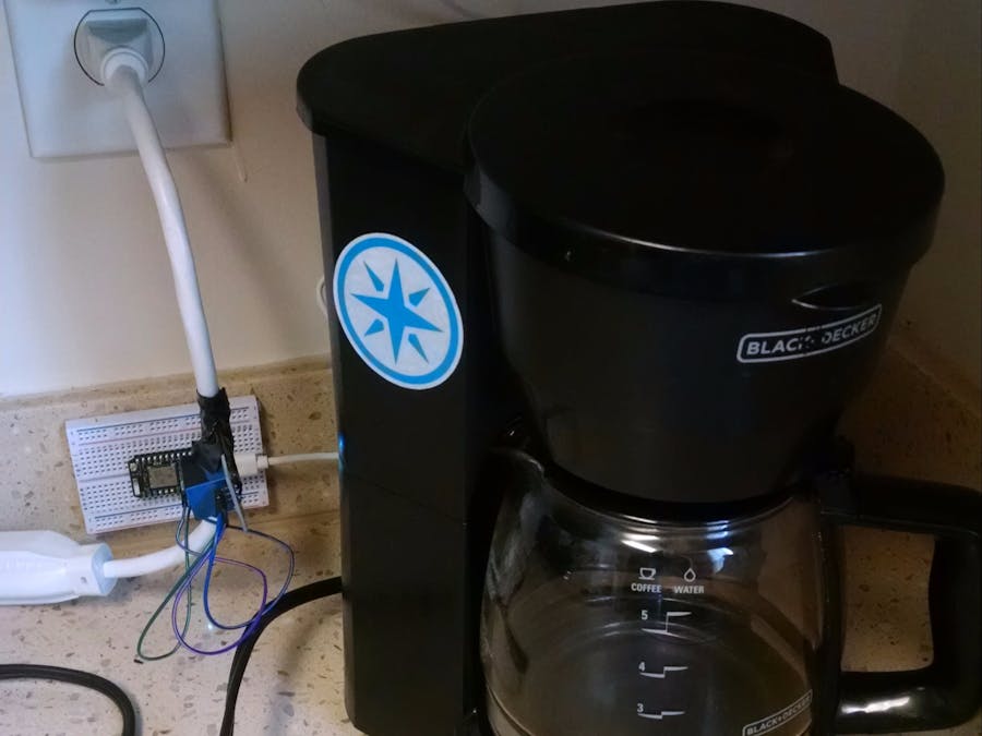
Alarm Circuit:Pictured below is the circuit containing the PIR motion sensor, the piezo buzzer (with a switch), the relay subcircuit described above, and of course, the Photon. The far right on the breadboard is power (red) and the far left is ground (black). These connect back to VIN and GND on the Photon. The black and white wires furthest left in the picture connect to the leads from the extension cords and the COM/NO connections on the relay. The orange and yellow wires are all signal wires that connect to the digital pins on the Photon. We connected the relay signal to D7 since that pin has the on-board LED to indicate that the pin, and thus the relay, is on.
As shown in the flow diagram, the PIR sensor will sense motion and trigger three things: the buzzer (controlled by a switch), the relay/lights, and an event, published to the cloud for the second Photon to receive. The PIR sensor must be perched and aimed at the bed. The lights are programmed to turn on for two minutes before the alarm goes off, making it a more relaxing wake. If the end of the specified time range is reached, the program will automatically be triggered. After 15 minutes, every digital pin is set back to off and the program is stopped. The system will power off based on the wall outlet timer, and when it powers back on the next morning, the whole thing will repeat.
Coffee Circuit:Upon receiving the published event from the first Photon via the cloud, the second Photon will subscribe to that event and subsequently execute a function that brews coffee. By the time you make your way out of bed, the coffee will already be made!
This circuit is much simpler than the first, as it only deals with a relay module. connected to a Photon and another modified extension cord. Simply connect the two leads from the extension cord to COM and NO, and for the Photon, connect GND to GND, VCC to VIN, and IN to any digital pin. The relay/coffee maker is programmed to turn off after 20 minutes.
An additional feature here is that this can be used as a WiFi coffee maker as well. The code is such that if you change the argument of a function in the cloud, it will brew coffee just the same. This can easily be done through Mobicle, a website created by Control Everything that allows you to track all variables and functions registered with the selected Photon, and to change the argument for a function to make it run. It accepts the arguments "On" "Brew" "on" and "brew". Here's what it looks like:
www.mobicle.ioVideo:
Here is a video showing our project in action!
Project Schematic
***Correction: "PID" should read "PIR," representing the PIR motion sensor for D0 on Photon1***


Comments
Please log in or sign up to comment.