Description:Make your own personalized useless robot. We've all seen the useless box but now you can create your own. This is an easy project and you can leave it on your desk at work and indulge in hours of procrastination. Please watch the video below to see how it works!
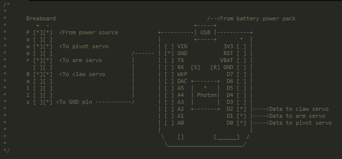
Instructions:Step 1 - Construct Robot CircuitThis circuit will control all three of the motors and move the robot arm. See below for detailed circuit schematic and a copy of the code used to control the motors.
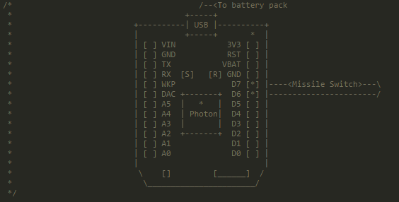
Step 2 - Construct Switch CircuitThe circuit shown below will send the data from the switch being flicked to the Photon you just connected. The data from this code will then be recorded and you can see the reaction time of the robot. See below for downloadable code and circuit schematics. This photon is not required for the robot arm to turn off the switch.
Step 3 - Print Your Robot!Use a 3-D printer to print all of your robot parts. This will take between 5-6 hours to complete. The CAD drawings for the robot are ready for download at the bottom of the page.
Printed parts may require light sanding or scraping on unfinished surfaces that come in contact with other parts (for example the printed piece that connects to the servo). Ensure the surface is smooth and the parts fit together snug.
While your robot is printing, it may be a good idea to cut your metal rods into 6 - 6" pieces (servorods), 2 - 5.5" pieces (servosliderods), and one - 1" piece (postrod). Once these are cut using your hacksaw you must file down the edges of the rod so they will fit smoothly into the holes of your printed parts.
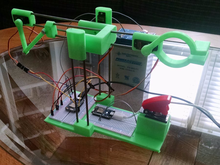
Step 4 - Assemble RobotOnce all of your parts are acquired, cut and filed you may begin to assemble your robot.
- Place all the 3D printed pieces where they should go to get a test fit as shown in the final assembly photo with the metal rods. At this point you may need to do some additional sanding to make sure everything fits together as designed.
- Use superglue on any loose attachments (for example where the metal rods slide into the placement holes on the base).
- Place servos, breadboards, and missile switch in their proper places. Sanding may be required.
- Connect wires to all circuit components using the schematics below.
Step 5 - Enjoy!We hope you enjoyed seeing how we made a Useless Robot, please let us know if you decide to make your own!
Graph:Below is a graphical representation of the response time of the robot hitting the switch. A data point is collected each time the robot hits the switch. From the video above, the response time was calculated. The length of the switch on time (1) is different because the robot taunts are variable times.


Comments
Please log in or sign up to comment.