Background
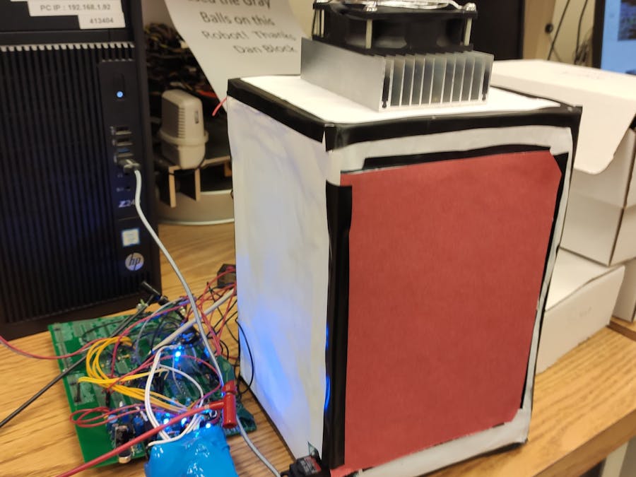
In this project, a small scale cooler using a Peltier module. Peltier module is a DC device which receives heat from one face and rejects heat to the other. This module has heat sinks and DC fans on both sides. The cold side is towards the space that needs to be cooled, in our case the inside of the box and the hot side is towards the ambient.
Aim
This project aims to control the Peltier module to maintain a particular temperature setpoint using the MSP430F2272.
Design
The following functionalities of the MSP430F2272 were used.
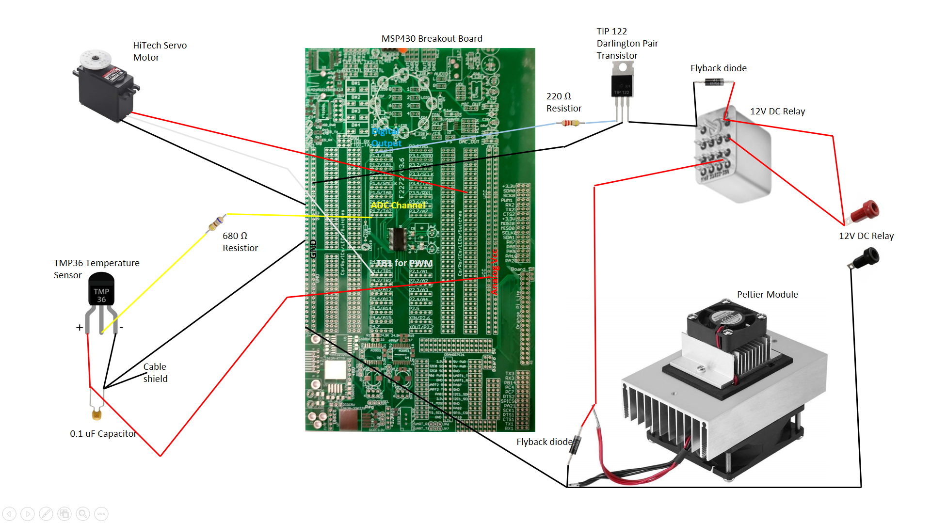
- Digital I/O pinsWe used the digital I/O pins to turn ON/OFF the Peltier module and the fan based on the temperature reading. We also used four switches to connected to P2.4 to P2.7 digital I/O pins to turn ON/OFF the fan on the hot side, OPEN/CLOSE the door. The circuits which allow these controls are discussed below.
- ADC10The 10-bit analog-to-digital ADC10 converter was used to convert the voltage readings of the TMP36 temperature sensor to temperature values (in °C). The raw voltage reading (in mV) and the processed value (in °C) are displayed in the Tera Term using UART_printf function.
- Timer BTimer B is used to control RC servo.
An on-off controller (bang-bang controller) was designed to control the Peltier module and the fan on the cold side. When the temperature goes 0.5 °C below the set point temperature, digital I/O would turn the Peltier module OFF and when the temperature goes 0.5 °C above the setpoint, the same digital I/O would turn the Peltier ON.
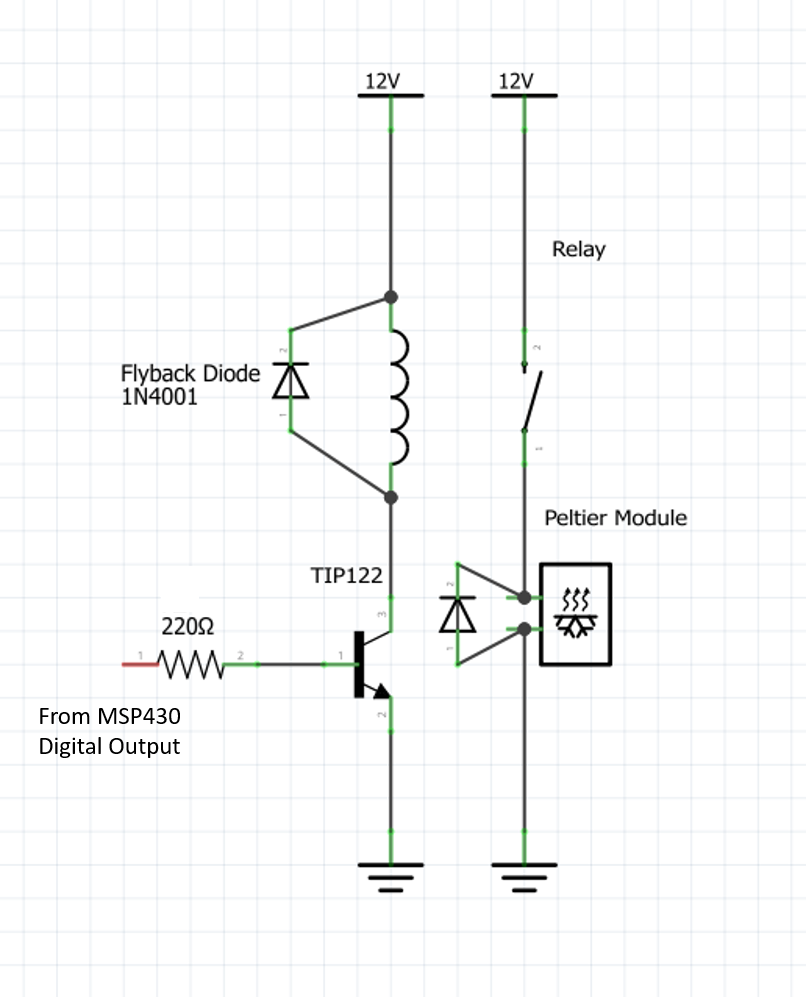
Digital I/O pin was used to turn ON/OFF the Peltier by using a circuit consisting of a 12V/5A relay, TIP 122 transistor, flyback diode, and a resistance.
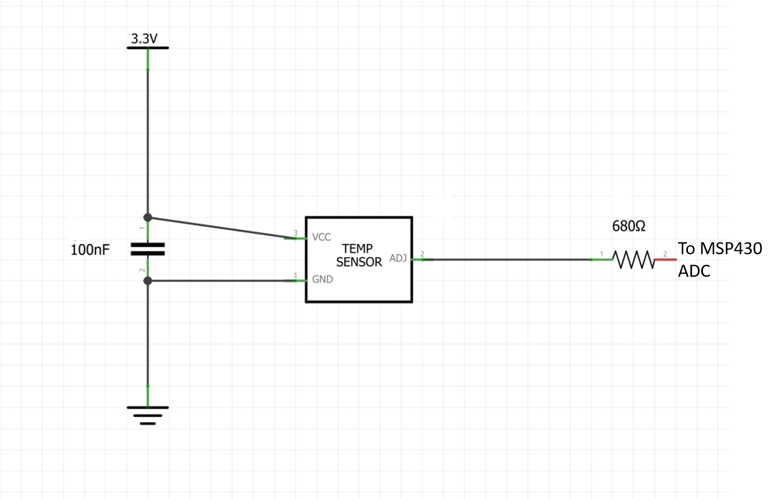
Shielding of the temperature sensor TMP 36To use an on-off control, we need an accurate temperature reading. Initially, we used the TMP 36 without any shielding. However, there was a lot of noise from ambient and other devices. An accurate temperature sensor reading was crucial for control. Significant noise in the temperature reading would cause the microcontroller to turn ON/OFF the Peltier module unnecessarily. So, we had to use a shielding circuit to eliminate this noise.
Opening and closing of the doorTimer B0 is used to control an RC servo attached to the door. A carrier frequency of 50 Hz is used. PWM signal is varied between a duty cycle of 8% (OPEN position) and 13% (CLOSED position). One of the switches is used to change the duty cycle from 8% (OPEN) to 13% (CLOSED) and vice-versa.
Results


Comments