


Hardware components | ||||||
 |
| × | 1 | |||
 |
| × | 1 | |||
| × | 1 | ||||
| × | 1 | ||||
| × | 1 | ||||
 |
| × | 1 | |||
 |
| × | 1 | |||
| × | 2 | ||||
 |
| × | 1 | |||
| × | 1 | ||||
| × | 1 | ||||
 |
| × | 1 | |||
| × | 1 | ||||
| × | 1 | ||||
Software apps and online services | ||||||
 |
| |||||
| ||||||
 |
| |||||
Hand tools and fabrication machines | ||||||
 |
| |||||
 |
| |||||
 |
| |||||
 |
| |||||
 |
| |||||
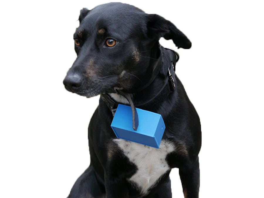
Animals have a major part in our lives. Thereby, we've developed an autonomous, user friendly, Wireless and substainable systemto help take care of your pet or animals in general (of medium and large category).
This system is a box put on an animal necklace. It can track its position, measure its temperature and its heart rate and also deduct its movements.
This system development requires you to have some knowledge in electronics, in computer science and in PCB making.
First step PCB makingThis system is composed of 2 PCB. A principal which contains all sensors and the microcontroller. A second one which is use for the power management.
There are the files to make PCBs by a PCB maker in the schematics and circuit diagram part.
- Sensors PCB On the pictures below you can see the Sigfox Wisol Module footprint on the left, then the GPS one on its right. There is the nucleo microcontroller one above this and the accelerometer footprint on its right. As you can see, there are pin holes Inside the microcontroller footprint. These are here to put the temperature sensor and the heart rate sensor out of the box, Inside the necklace to be the closest to the animal's neck.
- Blue : Sigfox Wisol Module
- Yellow : GPS Module
- Orange : Accelerometer
- Green : Nucleo Microcontroller
- Red wires : via
- Others wires : temperature and heart rate sensors deported out of the box
Solder headers and wires as on the picture !
- Energy management PCB This PCB will contain connectors to the battery and the solar panel, 2 polulu LDO, the 2 resistances, the capacitor and the charge manager MCP73831.
Solder headers as shown on the 2 first pictures above. Then solder under the microcontroller the MCP73831, the résistance and capacitors (1nF on the left and 4.4nF on the right) as shown on the third picture above.
Now you can add Polulus.
On your solar panel there are 2 pins. Solder these to long wires (approximately 20cm). Put them along the solar panel and ensnare them with liquid glue to not make it movable anymore.
We've developed a source code for the system on Mbed. The code :
- Initializes all sensors' registers
- Makes a temperature acquisition
- Takes 30 seconds of heart rate samples to get the better accuracy and adapts datas to be understandable
- Makes an acquisition of the GPS datas and extracts longitude and latitude
- Sends all datas to Sigfox backend.
- Put the microcontroller in sleep mode during 10 minutes
- The accelerometer counts the number of the animal's movements and rise an interruption each time he moves (so he is independant of the rest of the system). In fact the interruption wake up the microcontroller to increment a variable and it returns in sleep mode.
The source code is in the code part of this article
Put the code into the microcontroller. Then desolder the following Solder Bridge (SB) and LEDs circled on the 2 pictures below.
It is important to do this in order to save Energy.
- SB2 & SB3 : unlink the ST-Link, then it will be impossible to reprogram the microcontroller as long as these SB is desolder
- SB9 : allows to use Sigfox Wisol module and GPS on the same pins
It's time to link your Sigfox module to Sigfox backend and the last to ubidots.
- First, activate your module on Sigfox activate website (the device ID and PAC id are located on the Sigfox module packaging).
- Then create a ubidots account and a device (follow the steps shown on the pictures below).
- Next remember ubidots' token.
- Afterwards sign in to Sigfox backend (id : module_id@yopmail.com). And follow the steps shown on the pictures below.
The Sigfox callback body content :
{
"temperature" : {"value":"{customData#temperature}","context":{"Latitude":"{customData#latitude}","Longitude":"{customData#longitude}"}},
"deplacement" : {"value":"{customData#deplacement}","context":{"Latitude":"{customData#latitude}","Longitude":"{customData#longitude}"}},
"position" : {"value":{"Latitude":"{customData#latitude}","Longitude":"{customData#longitude}"},"context":{"Latitude":"{customData#latitude}","Longitude":"{customData#longitude}"}},
"rtmcardiaque" : {"value":"{customData#rtmcardiaque}","context":{"Latitude":"{customData#latitude}","Longitude":"{customData#longitude}"}}
}
This indicates to the callback the number of values send, their names, and their references to variables defined in the custom payload config at the top of the page.
If you have a problem doing the callback, this tutorial can help you : tutorial Sigfox backend to ubidots.
Box makingNow the system is pratically ready ! It only needs a box to put all the components inside. Print the box.
The box's 3D print files are in the schematics and circuit diagram part.part.
After printing the box, make a little hole on one of the small size to let wires pass.
Then everything is almost ready.
- Plug all components on the sensors' PCB.
- Put the sensors' PCB into the box.
- Put the free wires into the box hole.
Afterwards, make the same thing for the energy management PCB. Plug the battery. Finally put the solar panel's wires from out of the box into it through the box hole and plug it in the energy management PCB.
Close the box with sliding part.
Temperature & heart rate sensorsThe free wires out of the box must be linked to sensors ! So add to them sheaths and solder them to the temperature and the heart rate sensors.
Use scratch fixing system with double sided tape. We recommande to put the box at the bottom of the necklace.
Do the same for solar panel. We recommand to put the solar pannel on the top of the necklace.
Unpick the necklace sewing and put wires inside.
For the 2 outwards sensors do the same for their wires and make a hole on an inside side of the necklace to let them appear on the side neck of the animal.
Sew up the necklace.


_3u05Tpwasz.png?auto=compress%2Cformat&w=40&h=40&fit=fillmax&bg=fff&dpr=2)

Comments
Please log in or sign up to comment.