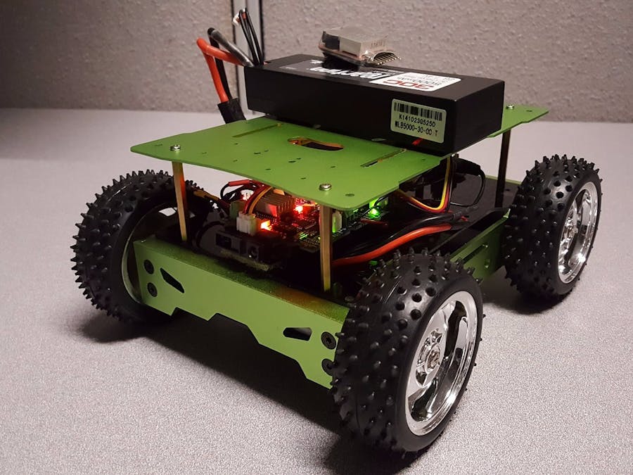
This project is an extension of the Arudino101 BLE Rover, where I had supplied some Seeedstudio Skeleton Bot 4WD mobile robotic platform kits to a team conducting a Maker experience for Oakland, CA High School students. The intent of this tutorial is to show how by adding sensors you can create a platform to explore how to program an autonomous self driving vehicle.
The high level sections for this tutorial are:
1. Assemble the basic rover
2. Programming the basic rover
3. Troubleshooting
4. Adding autonomous mode
5. Final comments on further enhancements
Detailed Hardware Bill of Materials:1. Arduino 101 board
2. Grove Starter Kit for Arduino
- Grove Base Shield v2.0
- Grove Proximity Sensor
- Grove LED Socket v1.3 with Blue LED
- Grove Cables (4 ea.)
3. Skeleton Bot – 4WD Mobile Robotic Platform
- Aluminum chassis and drilled acrylic plates - part of
- 25GA-370 DC motor (4 ea.) with wires for + and -
- Grove I2C Motor Driver Board with 0.25” standoffs, screws (2 ea.)
- 85mm Wheels, axels, screws (4 ea.)
- 1” Aluminum standoffs, screws for mounting Arduino
- Dean’s male pigtail for connecting to motor driver
- Dean’s “T” – 2 female connectors tied to one male connector
- Dean’s male with Arduino barrel jack
- Dean’s female to Traxxas connector
- Traxxas Li-Po 30C 5000mAh 2S 7.4V Battery
This project is based on the Arduino 101 BLE rover, so you can review the Assemble the Rover and Electrical Assembly Steps. I have added detailed directions, as I have changed the orientation of the Arduino101 mount point, and use a second motor controller to reduce likely hood of loose wires after collisions.
Mount the Arduino101 and Motor Controllers – Mount the Arduino101 onto the acrylic mounting plate and secure it with the metal screws. Mount the motor controller onto the acrylic mounting plate and secure it with the small metal screws. Set the motor controller so that the one mounted in the middle is 1, and the one in the front is 2 (see figure 1).
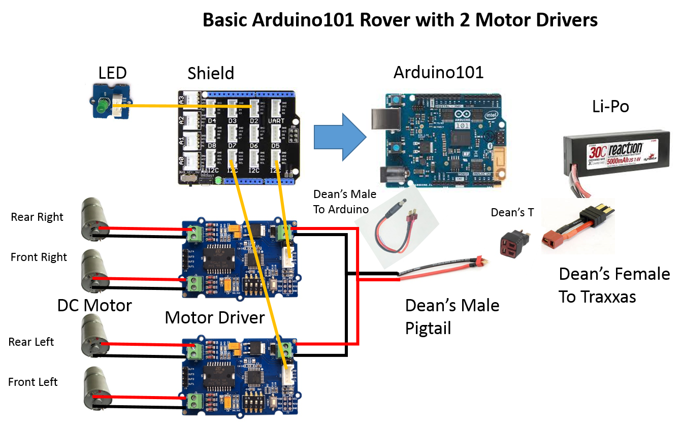
Assemble the power cables – The battery pack splits the output between the motors and other devices. Assemble the power cables as shown in the picture (see figure 2).
Power cables and motor wires – Pass the power cables and motor wires through the acrylic mounting plate. Note the location of the motor controller terminals; try to route the motor wires closer to them (see figure 3).
Wire motors to motor controllers – There are a total of 8 wires (2 per motor) color coded in pairs. Connect each motor to the motor controllers based on the following: right side motor wires go to the motor controller terminals in the middle of the chassis; left side motor wires go to the motor controller terminals in the front of the chassis (see figure 4).
Wire power cables – Wire the power cables to the motor controllers (red is positive, black is negative). Make sure to tighten all terminals to prevent wires from disconnecting (see figure 5).
Installing the Grove Shield – Insert the Grove shield onto the Arduino breakout board. Connect the motor controllers to the Grove Shield in any I2C labeled port using the Grove cables (see figure 6).
Mounting the Acrylic Plate and Add Sensors – Secure the acrylic plate to the main chassis using the four brass connectors. Connect the Grove LED to Grove Shield port D2 (see figure 7).
Mounting the Aluminum Plate – Secure the aluminum mounting plate on top of the acrylic mounting plate using the screws (see figure 8).
Installing the wheels – Install the 4 wheels onto the drive shafts (see figure 9).
Connect the DC barrel jack to the Arduino 101. Connect the Li-Po battery to the Dean’s male Traxxas connection. Connect a USB programming cable to the Arduino 101 and to your computer.
You'll need the Arduino IDE installed on your computer, with the Intel Curie Core (see Arduino 101 getting started.) If you are new to Arduino, it’s a good idea to run in the Arduino IDE File -> Examples -> 01.Basics -> Blink to verify that everything is working. The blinking on board LED can be seen from the side of the rover under the Grove Shield. Once that is verified you can load the code, which is in the project code section.
I use the same Arduino101 and Grove Motor Controller as the Programming the Arduino101 for a basic rover so check it out for an overview of how BLE is setup, and the motors are controlled using the Grove Motor Controller. Since the original base model code used one motor controller, and two are used here, there are some basic changes that I had to make.
However, the first major extension that I added was to process the whole UART transmitted string instead just the first character. This allows the commands between the rover and the BLE mobile device to be more human readable. For example, “a” go forward became: “Auto:Up” and “b” turn left became: “Auto:Left”.
This also means that the BLE Mobile control interface using nRF toolbox UART needs to send different strings than that of the original project, which used single characters for movement. In this project:
- “
Auto:Up” Moves the rover - Forward
- “
Auto:Left” Moves the rover - Left
- “
Auto:Right” Moves the rover - Right
- “
Auto:Back” Moves the rover - Reverse
- “
Auto:Stop” Stops the rover
You can configure nRF toolbox to act as a mobile BLE interface, by following these steps:
1. Install nRF Toolbox for your mobile device in either the iOS or Android app store.
2. Launch the nRF Toolbox on your mobile device.
3. Select the UART icon. There are nine user definable buttons in a 3x3 grid. If this is the first time, the default layout is called UART and blank.
4. Press the ‘EDIT’ button in the upper right corner.
The grid color will turn orange indicating it is in ‘Edit’ model. Touching an individual button in the grid brings up a setup screen where you can pick an icon for that button, and enter the appropriate string. Do this for all 5 rover commands. You can save this to another name (see figures 10-12).
5. Select the ‘DONE’ button to run.
6. Select ‘CONNECT’.
7. Select the BLE name from your Arduino sketch, 4WDUART for example.
8. Press the defined buttons to move the rover.
9. Press ‘DISCONNECT’.
10. Exit the app.
Section 3: Basic troubleshootingIf the motors do not turn at all, the I2C Grove Motor Drivers my need to be reset via a small button on the board (see figure 13).
To verify that the wiring was done correctly, sample code for the motor drivers can be used. Please reference the Testing Motor Control step of Arduino101 BLE Rover project this is based on for more details.
To verify BLE connectivity, nRF Connect for mobile can be used. Please reference the Arduino101 BLE Rover Remote Control for more details.
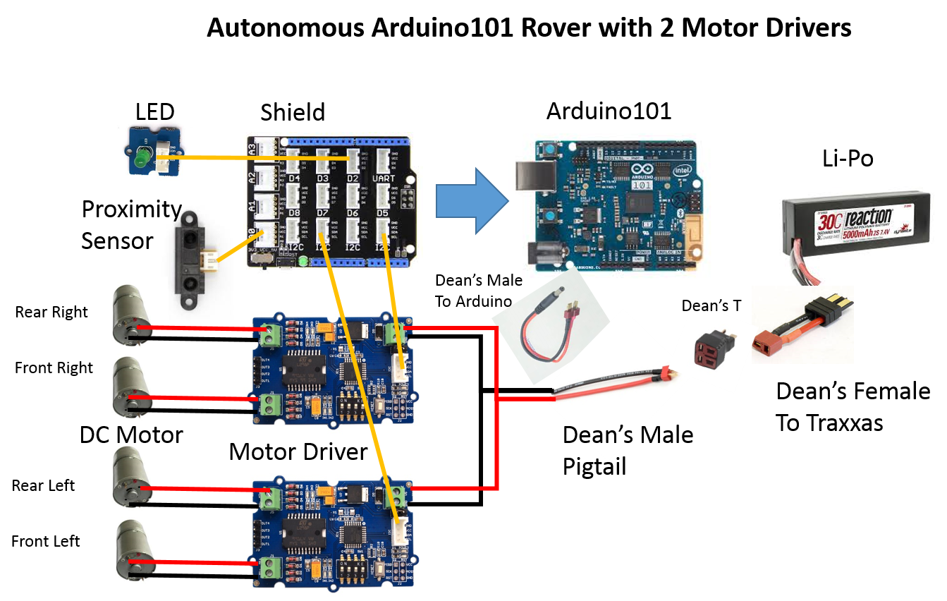
Section 4: Adding autonomous modeI added a Grove 80cm Infrared Proximity Sensor to the front of the rover to detect oncoming obstacles. It is attached to the Grove shield at port A0 by a Grove cable. By using the code snippet on the sensor’s wiki, I found that I could detect obstacles with enough time to react when the analog voltage was >1. With the second major extension of the base rover code, I added support for an autonomous mode, where when the UART sends a string “Auto:Auto” the rover drives forward until an obstacle is detected, and then the rover will alternate turning left and right for avoidance.
To modify the nRF Toolbox to support the autonomous mode, follow these steps:
1. Launch the nRF Toolbox on your mobile device.
2. Select the UART icon. Select the UART layout that you had configured for the basic rover.
3. Press the ‘EDIT’ button in the upper right corner. The grid color will turn orange indicating it is in ‘Edit’ model. Touching an individual button in the grid brings up a setup screen where you can pick an icon for that button, and enter the appropriate string. Touch an unused button, and set the icon to play and set the string to “Auto:Auto”.
4. Select the ‘DONE’ button to run.
5. Select ‘CONNECT.
6. Select the BLE name from your Arduino sketch, 4WDUART for example.
7. Press the defined buttons to move the rover.
8. Press ‘DISCONNECT
9. Exit the app.
Section 5: Final comments and further enhancementsThis project builds on top of the original Arduino101 BLE rover by using sensors to create a platform where developers can try their hands at programming an autonomous vehicle. Things to explore further on the rover code are: more sophisticated obstacle avoidance, multiple proximity sensors to allow the rover to detect and react to different types of collisions, different types of sensors to optimize for lighting conditions. Things to explore further on the BLE device are: interfaces beyond the simple digital 3x3 button grid like an analog joystick, or steering wheel and an accelerator pedal, and controlling multiple rovers from the same BLE central device at the same time. Things to explore further on use cases are: real world implementation of a go-cart video game with sensors detecting powers ups, robotics challenges like line following.


_baVEVgguW1.jpg?auto=compress%2Cformat&w=48&h=48&fit=fill&bg=ffffff)


Comments
Please log in or sign up to comment.