


Hardware components | ||||||
 |
| × | 1 | |||
_ztBMuBhMHo.jpg?auto=compress%2Cformat&w=48&h=48&fit=fill&bg=ffffff) |
| × | 1 | |||
 |
| × | 1 | |||
 |
| × | 1 | |||
 |
| × | 1 | |||
Software apps and online services | ||||||
 |
| |||||
Hand tools and fabrication machines | ||||||
 |
| |||||
| ||||||
| ||||||
Stuck at home with a little sports fanatic? This easy to build, Arduino-powered basketball hoop buzzer creates a fun, indoor basketball game. This project is also for beginners, so it is a nice first, second, or third project that you can build with kids.
Step 1: Gather the MaterialsHere are the Arduino-related materials needed for this project -
- Arduino Uno (You can also use an Arduino Nano or any other clone board of the Uno - I use an Elegoo Uno R3 for these tutorials)
- HC-SRO4 Sensor (A common sensor that can be used for a variety of projects)
- ACTIVE Buzzer (The output buzzer noise for this project. Make sure it is an ACTIVE Buzzer. Passive Buzzers make the 8 piano notes. Active Buzzers make the Buzzer noise.)
- Any Breadboard
- Some jumper wires (A lot of male-female and male-male, but maybe only 1-2 female-female)
- Lastly, the Arduino IDE software on Mac, Linux or a Windows device.
And here is everything else that you need -
- Some tape (Any type of tape is fine, but Duct tape, Flex tape, and any Heavy Duty tape will be way too big)
- A bucket for a basketball hoop (Get creative! - just remember that there should be no hole in the bottom - it needs to be covered since that is where the HC-SRO4 Sensor goes.
- A stuffed animal or a squishy ball that you know will not damage the sensor.
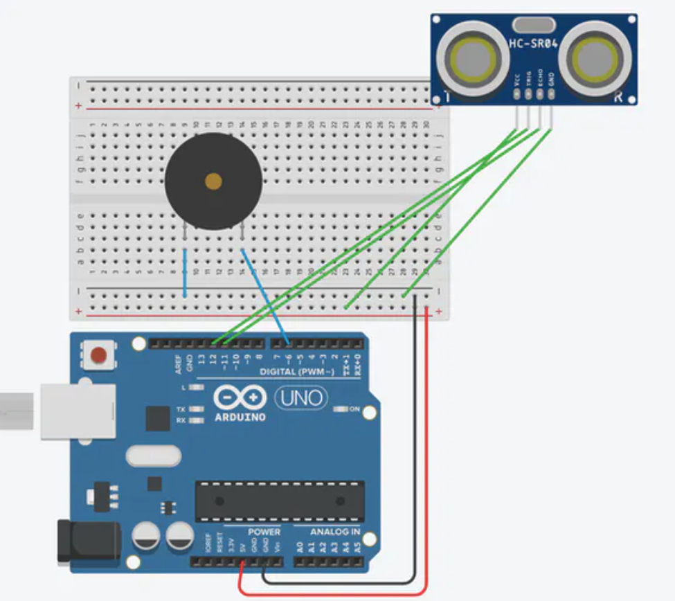
Part1-Understanding the basic Breadboard design
The Breadboard contains regular pins and positive and negative currents on the sides. Due to the fact that the Arduino only has 1 5V pin, and since most medium to decently large-scale projects involve multiple devices that run on 5V, you can connect that 5V pin to the top of the positively charged row. This will make any pin attached to the positively charged row receive 5V of power. Do the same with GRND and the negatively charged row. Although we only have one device that runs on 5V in this experiment, it is good practice now while you are practicing beginner projects, so the transition will not be as hard.
Part2:BuzzerSetup
The next step is to add a buzzer. One side goes to the Digital pin 6 (or anywhere else- just remember to change the code as well), and the other has a jumper wire going through to the negatively charged row (GRND). Pretty self-explanatory, right? The next step is where it gets tricky.
As you can see, assembling the buzzer part of this project is simple.
Part3:Sensor
If the images are not clear, here is the breakdown.
VCC --> 5V power (positively charged row)
Trig pin --> Digital Pin 12
Echo pin --> Digital Pin 11
GRND --> GRND (Negatively charged row)
Sounds easy, right - but wait! There's one catch -- The wires for the sensor need to be composed of at least three smaller wires connected since the sensor has to be reached and taped at the bottom of the basketball hoop.
Good job! You have officially finished the hardware portion of this project. Now on to the code portion.
Step 3: The CodeI will have a step-by-step guide and instructions about the code below. But first, copy and paste the code into Arduino IDE.
const int trig_pin = 12;
const int echo_pin = 11;
const int buzzer_pin = 6;
int distance_cm;
long duration;
Here, we are defining the variables. Remember the digital pins? Here we are saying that the trig pin is on 12, the echo pin is on 11, and the buzzer pin is on 6. We are measuring the distance with the sensor in centimeters, and its duration is labeled as "long".
void setup()
{
//Setting up the sensor
pinMode(trig_pin, OUTPUT);
pinMode(echo_pin, INPUT);
pinMode(buzzer_pin, OUTPUT);
}
Here we are setting up the sensor. To be more descriptive, we are setting the trigger pin (the pin that outputs the signal that something is detected) as output and the echo pin (the detecting pin) as input. This is necessary for almost any project with the sensor.
void loop()
{
//Sensor detecting movement
  digitalWrite(trig_pin, LOW);
  delayMicroseconds(2);
  digitalWrite(trig_pin, HIGH);
  delayMicroseconds(10);
  digitalWrite(trig_pin, LOW);
  duration = pulseIn(echo_pin, HIGH);
  distance_cm = (duration*0.034)/2.0;
//If the movement is far away, do not turn the buzzer on
  if (distance_cm >= 10 || distance_cm <= 0)
  {
  digitalWrite(buzzer_pin, LOW);
  }
//Otherwise, turn the buzzer on
  else
  {
  digitalWrite(buzzer_pin, HIGH);
  }
}
The first few lines, labeled, "Sensor detecting movement" are setting up how the sensor detects motion.
The if statement says that if the movement is far away, do not turn the buzzer on (As mentioned). However, the "else" part means that if it is close by, the buzzer should be on.
And that's the code! Now on to installation! :)
Step 4: InstallationOK, now lets physically install it. The project may not look like much, but with a bit of creativity and maybe some crafts, you can create an amazing creation to enjoy.
The only real step in this process is to tape the Sensor down onto the bottom of the bin. Make sure the wires are straight, and tape those down as well.
Plug it into your power supply, and then get shooting. Remember to use a very soft squishy ball or some sort of balloon, because if you use anything too heavy, your sensor could be damaged.
Here is the video of the project (Note - Arduino Nano shown in the video, but the project is easiest with an Arduino Uno)
Interested in this project? Here are my other projects - https://create.arduino.cc/projecthub/ShreyanR/lego-gun-shooter-with-an-arduino-uno-d9028a?ref=user&ref_id=1536504&offset=0
https://create.arduino.cc/projecthub/ShreyanR/soundbox-826a56
More projects coming soon!!!


Comments
Please log in or sign up to comment.