Postolachi VasileOdajiu Tudor
Published

Monitoring and self-regulating processor temperature

The temperature will be monitored with an LED, and the regulation will be done with a fan which will be turned on at a certain temperature.

BeginnerFull instructions provided2 hours365
Monitoring and self-regulating processor temperature

Things used in this project

Hardware components

Raspberry Pi Zero
Raspberry Pi Zero
×1
Breadboard (generic)
×1
Ultrasonic Sensor - HC-SR04 (Generic)
×1
RGB Diffused Common Anode
×1
Through Hole Resistor, 150 ohm
×3
DC Motor, Miniature
DC Motor, Miniature
×1
Dual H-Bridge motor drivers L293D
Texas Instruments Dual H-Bridge motor drivers L293D
×1
Male/Female Jumper Wires
×10
Male/Male Jumper Wires
×5

Software apps and online services

Raspbian
Raspberry Pi Raspbian

Hand tools and fabrication machines

fan stand

Story

Read more

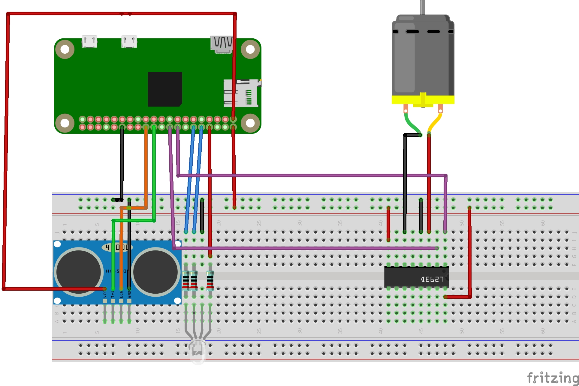
Schematics

Visual representation

Code

Code

Python
from gpiozero import CPUTemperature
from time import sleep  #we import the sleep module from the time library
import RPi.GPIO as GPIO #we import the RPi.GPIO library with the name of GPIO
import time

GPIO.setmode(GPIO.BOARD) #we set the pin numbering to the GPIO.BOARD numbering
GPIO.cleanup()
GPIO.setup(8, GPIO.OUT)  #we set the PIN8 as an output pin
GPIO.setup(10, GPIO.OUT) #we set the PIN10 as an output pin
GPIO.setup(12, GPIO.OUT) #we set the PIN12 as an output pin
GPIO.setup(16, GPIO.OUT) #we set the PIN16 as an output pin
GPIO.setup(18, GPIO.OUT) #we set the PIN18 as an output pin
GPIO.setup(22, GPIO.OUT) #we set the PIN22 as an output pin
GPIO.setup(24, GPIO.IN)  #we set the PIN24 as an input pin 

#we will set the pin  numbering to the GPIO.BOARD numbering for ultrasonic
trig = 22
echo = 24
#calculate distance with ultrasonic module
def calculate_dist():
   #set the trigger to HIGH
   GPIO.output(trig, GPIO.HIGH)
   #sleep 0.00001 s and set the trigger to LOW
   time.sleep(0.00001)
   GPIO.output(trig, GPIO.LOW)
   #save the start and  stop times
   start = time.time()
   stop = time.time()
   #modify  the start time to be the last time until the echo  becomes HIGH
   while GPIO.input(echo) == 0:
      start = time.time()
   #modify the stop time to be the last time until the echo becomes LOW
   while GPIO.input(echo) == 1:
      stop = time.time()
   #get the duration of the echo pin as HIGH
   duration = stop - start
   #calculate the distance
   distance = 34300/2 * duration
   if distance < 0.5 and distance > 400:
      return 0
   else:
      return distance

#the next variable stores the pin used to control the speed of the motor
motorspeed_pin = 16

 #the next variable store the pin used to control the direction of the motor
DIRA = 18
GPIO.output(DIRA, GPIO.HIGH) # set the  direction

#the motorspeed_pin will be used as an enable pin on the mootr driver
pwmPIN = GPIO.PWM(motorspeed_pin, 100)

#we start the pwm instance with a duty cycle of 0
pwmPIN.start(0)

counter = 1
try:
   while counter < 500:
      cpu = CPUTemperature()
      print(cpu.temperature)
      if cpu.temperature < 38:
         GPIO.output(10, GPIO.LOW)  #we change the digital output on the 10th pin to a low voltage
                                    #the GREEN LED stops
         GPIO.output(8, GPIO.LOW)   #we change the digital output on the 8th pin to a low voltage
                                    #the RED LED stops
         GPIO.output(12, GPIO.HIGH) #we change the digital output on the 12th pin to a high voltage
                                    #the BLUE LED starts
         pwmPIN.ChangeDutyCycle(0)  #set the speed of the motor to 0 (off)

      if cpu.temperature >= 38 and cpu.temperature < 45:
         GPIO.output(12, GPIO.LOW)  #we change the digital output on the 12th pin to a low voltage
                                    #the BLUE LED stops
         GPIO.output(8, GPIO.LOW)   #we change the digital output on the 8th pin to a low voltage
                                    #the RED LED stops
         GPIO.output(10, GPIO.HIGH) #we change the digital output on the 10th pin to a high voltage 
                                    #the GREEN LED starts
         if calculate_dist() < 15:
            pwmPIN.ChangeDutyCycle(100) #set the speed of the motor to 100 (on)
         else:
            pwmPIN.ChangeDutyCycle(0)   #set the speed of the motor to 0 (off) 
      if cpu.temperature >= 45:
         GPIO.output(12, GPIO.LOW)  #we change the digital output on the 12th pin to a low voltage
                                    #the BLUE LED stops
         GPIO.output(10, GPIO.LOW)  #we change the digital output on the 10th pin to a low voltage
                                    #the GREEN LED stops
         GPIO.output(8, GPIO.HIGH)  #we change the digital output on the 8th pin to a high voltage
                                    #the RED LED starts
         pwmPIN.ChangeDutyCycle(100) #set the maximum speed of the motor
      sleep(1)
      counter+=1
except KeyboardInterrupt:
   pass
GPIO.cleanup()

Credits

Postolachi Vasile
1 project • 0 followers
Contact
Odajiu Tudor
0 projects • 0 followers
Contact

Comments

Please log in or sign up to comment.