This project was made as part of a college tutored project. It is a work in collaboration with the University of New Caledonia and OPT, a local governmental company involved in telecommunications. It was done by two second year IT degree students and guided by an industrial tutor Adrien Sales (Division Manager at OPT-NC).
The initial goal was to build a device usable by companies to detect incoming objects in a mailbox in order to notify its owner, using a WiFi connection.
This article is intended as a guide for those who might need to build this device in the future.
Step One: ElectronicsThe first step of this project requires wiring all the components together correctly.
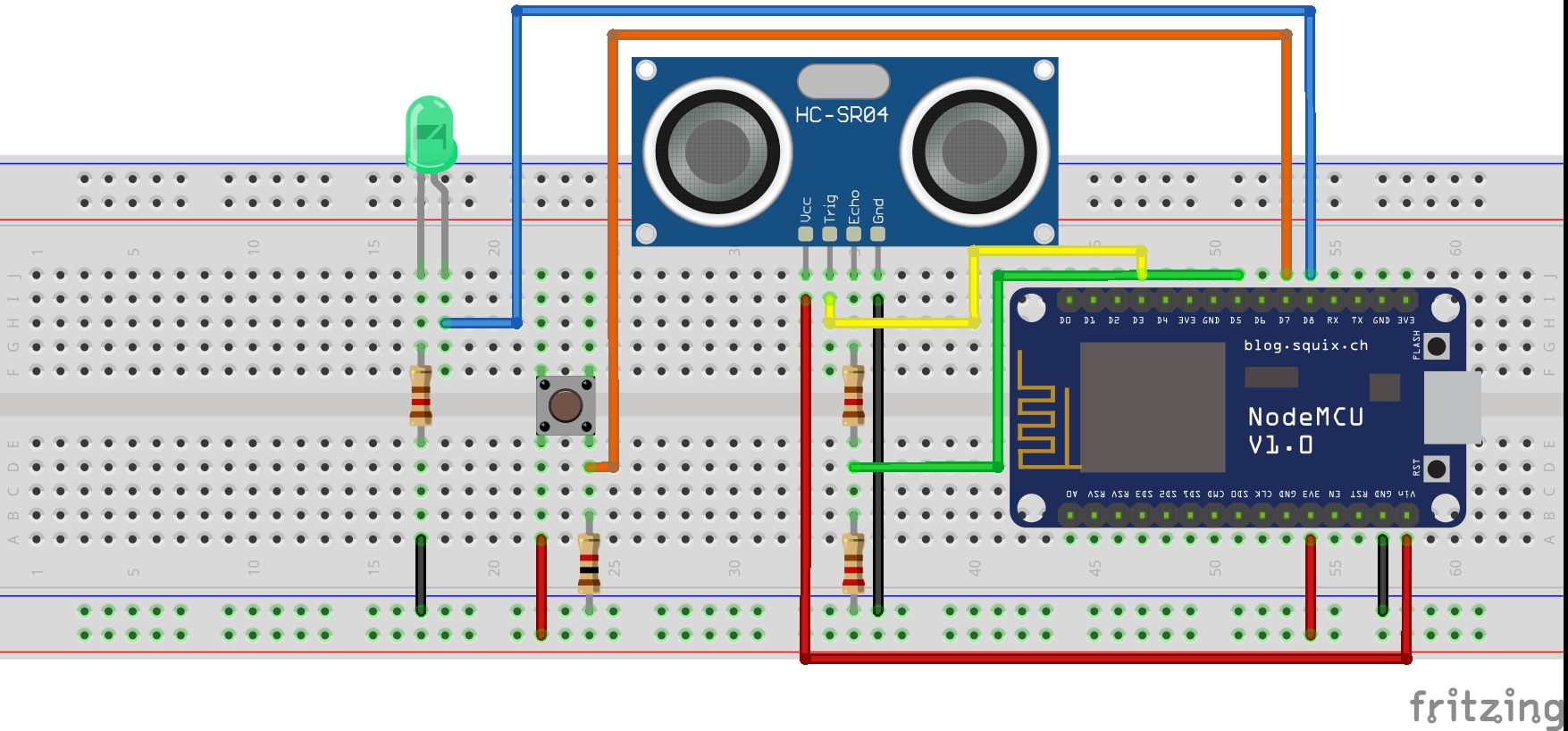
First, add the NodeMCU board and the HC-SR04 ultrasonic sensor directly onto the breadboard. Take note that the NodeMCU board works using 3.3V while the HC-SR04 sensor uses 5V. To be able to connect them together without frying anything, we've used a few tricks :
- USB connection provides 5V, which is then converted by the NodeMCU board to 3.3V. The VIN pin, usually used to provide power to the chip, is directly connected to this 5V alimentation. This means we can use it to power the HC-SR04 sensor through USB directly. Be careful when using any other power source than USB, as it might not provide exactly 5V !
- The HC-SR04 Trigger pin is an input pin. Luckily, a 3.3V signal is enough to trigger it, so we can directly connect it to the D3 pin on the NodeMCU chip.
- The HC-SR04 Echo pin is an output pin (5V), which means it cannot be directly connected to the NodeMCU chip. We use two resistors to divide the output tension to 3.3V, and connect it to the D5 pin. In order to do this, the first resistor needs to be about half the resistance of the second resistor (here we used 120 ohms and 220 ohms resistors).
- The ground pins of both chips need to be connected together.
The next step is to connect a push button to the D7 pin :
- Connect one side of the push button to 3.3V directly.
- Connect the other side to the D7 pin, and to a resistor connected to the ground. A relatively high resistance resistor is recommended, but any resistor should work. For exemple, we used a 1K ohms resistor.
Finally, connect an LED to the D8 pin :
- Connect the positive (long) side of the LED directly to the D8 pin.
- Connect the negative (short) side of the LED to a resistor connected to the ground. We used a 120 ohms resistor for this.
IFTTT is a freeware web-based service that creates chains of simple conditional statements, called applets. We use an IFTTT applet to forward the notification to the end user.
In order to use IFTTT, you will first have to create a free IFTTT account. Once connected, go to the create section to create your first applet, and click on the "+" symbol to start the creation of your applet.
Write down "Webhooks" in the search bar to find the Webhooks service, and select it. Click on the "Connect" button to connect the service to your IFTTT account for the first time.
Once done, select "Receive a web request", and enter an event name. It should describe this webhook's role simply. For exemple, we used "mailbox_detected_object" as our event name.
Click on "Create trigger", then on the "+", and select the service you would like to get notifications from. Any service available in IFTTT can be used, depending on your needs. For this tutorial, we will use the "Email" service to get notified by email when a new letter is detected.
In order to use the Email service, you will have to link it to your IFTTT account. Click on the "Connect" button, enter your email and hit "Send PIN". Then copy the PIN code you received by email. You should now be able to use the Email service. Select the "Send me an email" option.
The next step is to set up the message sent in the notification. You can add/remove ingredients, and edit the message to your liking. Here "Value1" is the number of letters received since the last notification, "Value2" is the total number of letters currently in the mailbox, and "OccurredAt" is the date and hour at which the webhook was triggered.
You can copy this message exemple to get started, and modify it if you'd like something different. You will still be able to modify the message after the applet is created.
You received {{Value1}} new letter(s).
You received {{Value1}} new letter(s) on {{OccurredAt}}<br> Total number of letter(s) in the mailbox : {{Value2}} <br>
Once you're happy with your message, click on "Create Action", and then on "Finish".
And that's it, you've created your first applet! You can turn it on by switching the "Connect" button.
For the next step of this tutorial, your IFTTT account's webhook key is needed. To find it, go to the webhook section and click on "Documentation".
Step Three: Setting up the Arduino IDEWe use the Arduino IDE to upload code to the NodeMCU board.
Because it is not included in the Arduino IDE by default, we need to manually add support for this board. First, open the Preferences menu ("File">"Preferences").
Enter the following link after "Additional Boards Manager URLs:" and confirm by clicking "OK".
https://arduino.esp8266.com/stable/package_esp8266com_index.json
Then open the Boards Manager menu ("Tools">"Board">"Boards Manager...").
Write "esp8266" in the search bar, and install the "esp8266" by "ESP8266 Community" package.
If everything was done correctly, you should be able to select the "NodeMCU 1.0 (ESP-12E Module)" board instead of your regular Arduino board.
Now that the Arduino IDE is ready, we need to install the required libraries for this project. Conveniently, all of them are from the esp8266 GitHub projet.
To install the esp8266 libraries. Simply download the code from GitHub and copy the content of the "libraries" folder into the Arduino IDE library folder. The default library folder for the Arduino IDE is located at "..\Documents\Arduino\libraries".
If pushing code to the board isn't possible at this point, you may need to install these drivers for the NodeMCU board to be recognized.
Step Five: Uploading the codeThe next step is to download and configure the code before uploading it to the board.
First, download the code from this GitHub repository. Make a copy of the file "config.exemple.h", rename it "config.h", and open it with a text editor.
Replace the WiFi informations to match with your WiFi network. Copy your event name from step 2 in the "trigger" variable ("mailbox_detected_object" is our event name), and your webhook key in the "key" variable (see step 2 on how to get it) before saving the file.
Next, open the "main.ino" file with the Arduino IDE and switch the board to "NodeMCU 1.0 (ESP-12E Module)". Connect the NodeMCU board to your PC through USB, and click on the arrow to upload the code to the board. It can take a few seconds for the code to be uploaded. Once it's done, the device should be ready to use !
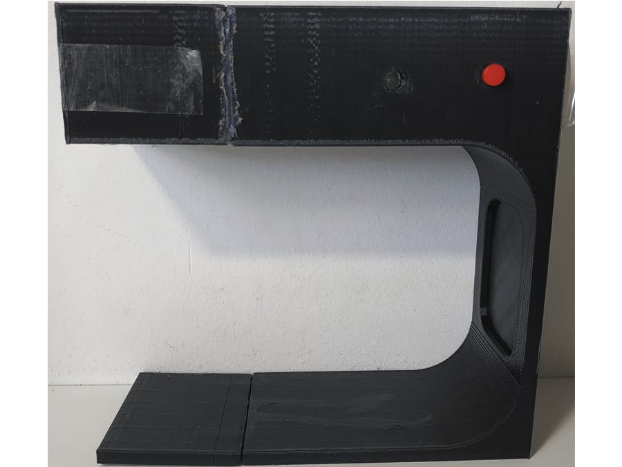
Step Six: Building the caseFinally, you will need a case to put the NodeMCU and breadboard in in order to properly install it. You can use our 3D model (linked at the bottom) to 3D print your own case. Don't forget to adjust the sizes to fit your mailbox !
If you do not own a 3D printer, you can always build your own case using cardboard ! It might not be the most elegent solution, but it works if you do not care about the look. For exemple, we cut this case out of a cardboard box.
Try to pass an object in front of the ultrasonic sensor, and watch how the LED changes patterns. After a moment (up to 30s with the default values) it should blink twice in a short time. This would indicate that the box was able to send the notification, and that everything is working as intended.
If not, double check your WiFi informations. If you can't figure out why your box is not working, if you have found a bug, or if you have any suggestions, please leave a comment below or on GitHub.
If that's the case, this tutorial is now over ! You can put the board inside your 3D printed model, then move the box inside your mailbox, wire it, and never miss a letter again !
Exemples:We experimented different notification methods, here are a few exemples :


Comments
Please log in or sign up to comment.