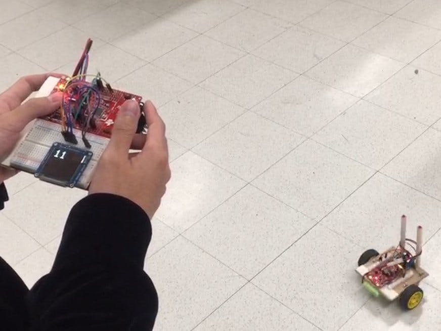
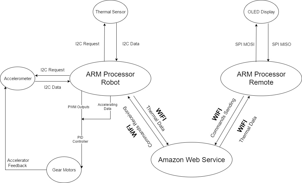
The robot stand on two lined wheels, and we tend to fall and lose its verticality. The movement of the wheel in the direction of the falling rises the robot for recover the vertical position. The car attempts to correct for an induced lean angle by moving forward or backwards, and the goal is to return itself to vertical. The car also detect the surrounding temperature and send to the Amazon AWS IOT, then we use the remote to get the temperature data from Amazon AWS IOT.
Mechanical Part- H-bridge:
- L298N as main driver chip makes strong driving ability/small heating/strong anti-interference
- Use large-capacity filter capacitors and diode with freewheeling protection function, increasing reliability
- This module integrated with one internal 5V power supply, meaning when you driving voltage is 7V-35V,it makes 5V of energy board power supply logically; when 5V of energy board power on, please do not input voltage to +5V power supply in interface but you can lead 5V voltage for external usage
Eg:
ENA enable IN1 IN2 to control OUT1 OUT2
ENB enable IN3 IN4 to control OUT3 OUT4
- 2 Gear Motor
With EMC, it has an anti-interference ability Operating Voltage: 3V ~ 6V DC
Rate: 125 rpm
- Structure
During the experiment, we have built three structures and finally developed a desired structure.
The wooden plank we used is 13.97 cm * 13.97 cm.
The first one we built has an inclined angle in horizontal. We try to make the car keep balancing itself with this angle, but it is too hard to implement control. The reason may be that the weight is unevenly distributed.
The second structure has two stages. The first stage is used to place battery and H-bridge. The CC3200 is placed on the second stage. The advantage of this design is that weight is even distributed through the whole structure and there is a higher sensitivity to inclination in order to give the launchpad more time to proceed. However, the disadvantage is that our motor is not powerful enough to balance the car on time.
We have found that keeping the center of gravity lower will make the rover less sensible to the oscillation. Therefore, we built the √third structure. Moreover, keeping the rover’s weight equally distributed helps the motors adjust the rover’s position quickly.
After taking the NETCAR senior project. We get familiar with PID control which is very useful for linear adjustment. At first, the car could stand with only the raw adjustment but it shaked fiercely and would fall into one direction at the end.
With proportional parameter, Kp, the speed of the motors are proportional to the rover’s axial tilt.
With derivative parameter, Kd, the speed of the motors are proportional to the derivative of rover’s axial tilt.
With derivative parameter, Ki, the speed of the motors are proportional to the integral of rover’s axial tilt.
With proper proportional, derivative, and integral terms, we can build a stable self-balancing system that reacts to falling very effectively.
During experiment, we found the values read from CC3200’s accelerometer were much smaller than expected values that can update PWM duty cycle effectively. As a result, we used relatively larger Kp in order to restore balancing position quickly.
Self balancing after falling:We set a counter and add 1 in every loop. When the car is fall into one direction and keep moving( >29 or <-29), the counter add 10 per cycle. Overall, we determine when the car should bounce back after 10000 counts.
PWM Timer SignalAfter playing with the pwm_demo project on cc3200, we used Pin 50 and Pin 59 for PWM outputs.
Accelerometer & Thermometer:CC3200 I2C implementation
- Accelerometer: device address is 24; register offset 5 for y-axis.
- Thermometer: device address is 65; register offset 1.
We are analyzing the buffer’s data in the http_get() function.
Here is the httpget function for the remote. When the buffer has the keywords of what we set, for example: "TEM", it started to get data "11" from Amazon AWS IOT server.
- When transmitting data from the launchpad to cloud server(http_get and http_post), the gpio pins went to crazy. After put the signals on the oscilloscope, we found a pulse after transmitting the signal. We guess the pulse is because the board needs to generate high current to sending or getting data by using its wireless function. The crazy gpio pin will make our car knock the ground at a very high speed. After hundreds of testing, we solve it by making motor have a quick pause (duty cycle reduce to zero). In this way, the data transmission would never have an impact on the self-balancing performance.
- Time limitation: We only have one week to brainstorm and finish our design. It is really short.
- The motors we purchased are not exactly identical to each other even they are supposed be the same. One of them rotates faster under the same voltage. So we could not run the car following a straight way.
The test run went very well, especially the rover’s ability of self balancing. The rover can recover balance very quickly after sudden and strong disturbance. If the rover falls, it would stop moving first, then CC3200 will give a current pulse to the motor so that the rover can recover balance immediately.
Overall, the performance of the rover also meets our expectation. With the control of the remote, it can go forward and backward. It can rotates and change its direction freely. The thermal data will be sent to the remote and displayed on the OLED.


Comments