


Hardware components | ||||||
| × | 1 | ||||
Software apps and online services | ||||||
| ||||||
| ||||||
| ||||||
| ||||||
Hand tools and fabrication machines | ||||||
| ||||||
| ||||||
| ||||||
| ||||||
We’ve all seen the old Simon Says game, where you try to copy a sequence of lights by pressing the button that corresponds to the correct light sequence. For Hackster Live we showcased a PCB design tool called Upverter. This is a fun and simple project to create and turn into a PCB. Below is the basic project showing the game creation complete with hardware and code.
There are three parts to this project series.
- Part 1: Making the Simon Says Game
- What a CAM software is and how to choose one
- How to create gCode from Upverter files using Otherplan
- How to use InkScape and Makercam to create gCode for through holes
- How to use a gCode viewer like CAMotics to test your gCode
- How to draw PCB traces using a CNC machine
- How to drill through holes using a CNC machine
- How to cut out your CNC machine
We'll be using the PCB design for the Simon Says Game that we created in parts one and two. This is what we'll end up with:
There are 5 parts to physically creating a PCB from Upverter using a CNC machine:
- Exporting your files from Upverter.
- Turning your files into gCode (code readable by the CNC machine). We're going to end up with four different files.
- Milling. This cuts the isolation traces by taking off the layer of copper from the top so that none of the traces touch.
- Drilling. This drills the through holes in the PCB.
- Edging. This is the last step. You cut the PCB free in the shape that you like.
Some CAD software lets you export directly to gCode, making this basically a two step process.
Upverter doesn't, but it exports gerber files (yes, like the baby food) and Excellon NC drill files for the drill holes. There’s software that can turn both of these into gCode for use in the Shapeoko or other CNC mills.
We are going to need four different gCode files to send to our Shapeoko or other CNC machine:
- Top side isolations
- Bottom side isolations
- Through holes
- Border & mounting holes
For our isolations, we'll import our Gerber files into a CAM software.
Choose a CAM SoftwareThere are a ton of different CAM softwares out there.
Flatcam seems to be the most popular free CAM software. Unfortunately, one of the requirements on Mac is pyqt4, which hasn’t been maintained since 2015, so I couldn't install it.
I ended up going with Otherplan Classic, which turns gerber files into gcode and is available for Mac and Windows.
I also used a great free online software called Makercam.com to turn the drill files into gCode.
Create the gCode for the TracesWe call our traces 'isolations' since they work by cutting the copper free of itself, isolating the parts that need to be separate.
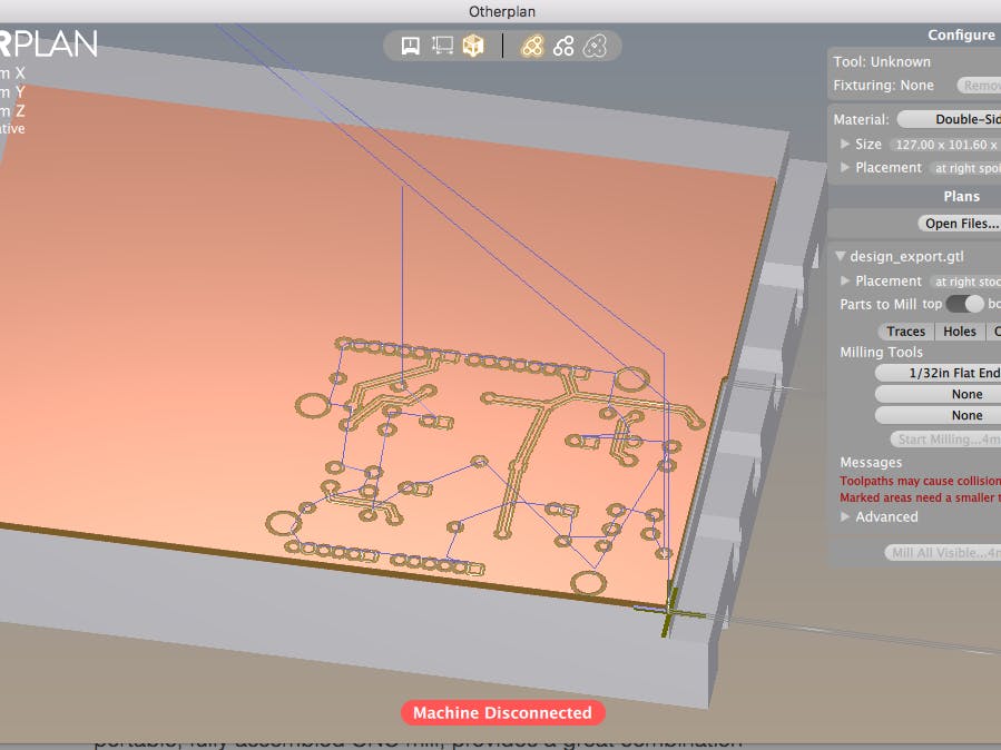
- In Otherplan Classic, select "Open Mill project." Open your .gtl file (this is the only file that Otherplan Classic recognizes). You'll see your project rendered in 3D.
- To convert to gCode from Otherplan, go to ‘Otherplan Classic”>”preferences” and make sure “bitbreaker mode” is selected.
- Now you’ll see a menu item called “bitbreaker” at the top of your screen.
- Make sure the top of the board is selected.
- Deselect the Outline, since we don't want to export it.
- Select your end mill size. We'll actually be using a 0.1mm engraving bit, but I selected '1/32nd inch end mill since this version of Otherplan doesn't have engraving bits as an option.
You’ll have to export the top and bottom in different gCode files.
- Select “Export visible plans.” This will only export the top isolations of the board.
- I named my gCode file “Simon_Says_Top.nc.”
Now select the bottom of the board.
- Select “Export visible plans” again.
- I named my second gCode file “Simon_Says_Bottom.nc.”
- Finally, deselect traces and select only the outline. Export this as "outline.n.c".
Note that there are different kinds of gCode. If you're using a CAM software and it gives you an option, be sure to choose Standard gCode.
Create the gCode for the Through-HolesI used Inkscape to open the .SVG file that contains my drill holes. You can also use Adobe Illustrator, or QCAD.
Here are the steps in InkScape:
- Open in InkScape the drill files (filename something like "xxxxxxxx_dimensiondrawing.svg.")
- Edit > Select All (Ctrl+A)
- Object > Ungroup (Ctrl+Shift+G), repeat until you see "No groups to ungroup" in the bottom
- Path > Stroke to Path
- Path > Union
- File > Save As *.svg (Inkcape SVG is fine)
Now go to makercam.com
- Select file > open SVG File
- Select through hole outlines
- CAM > Drill Operation
- Choose your tool diameter, target depth, and plunge rate. We're using an 8th inch drill bit for these holes. The target depth should be 0.005 inches deeper than the depth of your material. So if you're using 1.5mm board like we are, you'd change it to 1.627mm (you can convert the units in the upper right hand corner). Our plunge rate is 20 inches a minute, or 508 mm/minute.
- CAM > Calculate all
- CAM > Export gCode
Note that makercam has an issue with resizing files sometimes. I noticed this when I went to drill holes and the holes didn't even FIT on my PCB! To fix this, before importing your SVG, go to Edit > Edit Preferences > change the SVG import resolution from 72 to 90.
There's a great gCode viewer called G-Code Q'n'dirty toolpath simulator where you can see how your gCode will cut and approximately how long it will take.
Open your .nc file in textedit or notepad, and copy and paste the code into the the left hand window. Select “Simulate.” The grid in the image is the 0,0 axis, where the CNC will start. The red arrows show the path that the CNC will travel. If you select the lines of code, the bottom image will "step through" each action that the CNC will take.
What is the gCode doing?
The first command of the top CNC path is on line 17 (The simulator recognizes this and marks it in red):
N5G53 G00 z-0.500
It’s telling the machine to lower on the z-axis to 0.500.
If you want to know more about how to read gCode, Make has a great tutorial here.
The top traces look good.
Paste in the bottom gCode. The bottom looks accurate as well. The only problem is that I forgot to deselect the outline when I exported the gCode from Otherplan, so the outline is showing up. We'll be doing that with a larger drill bit after we've already milled the traces and drilled the through holes, so we want that to be in a separate gCode file.
Thankfully, the gcode exported from Otherplan Classic has nice comments, so I can easily find where the border is and delete it.
Align Top and BottomNow I want to make sure that my top and bottoms line up, so I paste the gCode from both into the interactive gCode viewer at the same time.
They both start from the same bottom corner, so I can drill a hole in (0,0) and know where to line the PCB material up when I flip it over.
Now I paste my through-hole gCode onto my traces gCode to check that. Oh drat! They don't line up!
It looks like each drill hole is approximately one mm to the right and above the trace files.
I tried to figure out what caused the discrepancy, but in the end, I just gave up and adjusted the drill manually to have a slightly different 0,0 when I drilled the holes.
IssuesYou may find some issues with your board when you export the gCode. One thing I noticed is that my traces overlap the mounting holes:
Interestingly, I also tried viewing the gCode using another CAM software, CAMotics, and some traces shown are bad:
Since I'm no gCode, expert, to be on the safe side I redid these areas in Upverter, exported them again as gerber files, and went through the steps of converting them to gCode again.
Milling the boardThanks to Richard Albrightton for his excellent write-up about milling PCBs with the Shapeoko here.
We'll be using Universal gCode Sender to send our gCode to our Shapeoko. This is an awesome free, opensource software and it's available on github.
The first thing to do before etching or drilling is make sure the surface is level. When milling a PCB, even the slightest variation in height across your copper clad board can ruin your isolation milling traces. There’s a helpful free software called autoleveller that should help with this.
You’ll want a piece of wood to serve as your ‘Sacrificial waste board.’ To help prevent this from happening, you’ll need a sacrificial waste board plain pine board or similar. This will ensure that your PCB is flat relative to the spindle.
You’re going to drill the pins first. You’ll want a drill bit for this, since you’ll actually be going through the board. We used an 8th inch drill bit, since that's what Richard recommended for boards that have male headers.
- Be sure to wear safety goggles. You don’t want to get copper shards in your eyes and lungs!
- Tape down the board or clamp it down. This will let us drill our reference points.
- Manually position the mill at the place you want to start near the board's corner. This will be the 0,0 axis. When your bit gets very close, open the chuck, let it drop to the board, and then adjust the drill manually so it fits.
- Drop the bit in, and tighten it up manually.
- Open Universal gCode Sender and in the software, select 'reset zero.' The Shapeoko will remember this as the zero axis until you either reset zero again, or turn it off.
- Now turn the shapeoko on and drill a hole manually at 0,0. This will be the alignment hole we use for aligning the board on top and bottom.
- Once this is done, select your file in Universal gCode Sender, open it and send it to the drill. I like to reset zero so that the Z axis is 5 mm or so above the board when I do this. This lets me test the file without actually drilling any holes yet.
- When you're sure your drill is going to be drilling in the right spots, reposition the drillbit at 0,0 and send the file again.
- The drill will go over each hole twice.
- Universal gCode sender has a helpful feature, 'Visualize', where you can visualize the parts that are currently being printed in the software.
The second thing that you’ll be doing is milling the top traces. You’ll want to switch out the drill bit for an engraving bit. We used a 30 degree engraving bit with a 1mm point.
- Follow the steps above to send the top engraving gcode.
- Be sure to do a test run first with the z axis raised!
What happens is something doesn’t etch completely? Just lower the z axis a tiny bit and do another pass.
Once the top traces have been engraved, flip the board over to mill the bottom traces.
- The 0,0 hole that was in the bottom left corner should now be in the bottom right corner.
- Zero your Shapeoko to the alignment hole.
- Send the bottom engraving gcode to the machine like we did in the steps above.
- Don't forget to do a test run first!
Now we're ready to cut the board free of the PCB.
"Every block of PCB material has a PCB inside it and it is the task of the engineer to discover it." - Michaelangelo
- Place your 1mm drill bit in the chuck.
- Flip the board back over to the top side.
- Zero your shapeoko to the alignment hole.
- Cut the board free!
All that remains to be done is solder the parts. This board has one problem. It involves soldering headers to non-plated through-holes. Since non-plated through holes need to be soldered on both sides, this is a nearly impossible task.
One way that I've seen suggested is trying to plate your own through-holes with conductive ink.
I ended up getting some PCBs manufactured through OSHpark. OSHpark is famous for their purple boards. They're based in Portland, Oregon, so they have super quick turnaround and reasonable prices for those of us based in the U.S.
Gather your components
The components for this project are all through-hole parts. We did this to make it easy to translate the breadboarded project to a PCB.
Place your components on the board
The through-hold components can be placed on the board easily. It's good to place them just to make sure they all fit correctly.
Solder your components
It's usually easiest to solder the parts that are closest to the board (with the lowest profile) first. That way you can stick them through the board and as you're soldering the board, the backside will hold them in place.
That means I solder the resistors first. Open the design in Upverter so that you can see which resistors types correspond to which resistor holes. I see that resistors 1-4 are 10K ohm, and resistors 5-8 are 330 ohm. Thanks to our silk screen, it's easy to find the correct resistor holes. Solder and trim the ends. Next, solder the buttons, and finally, solder the stackable headers (don't trim the ends on these).
Finally, solder the LEDs and the piezo. It's easy to figure out which way the LEDs should go without consulting the schematic - simply line their flat edge up with the flat edge (the bisecting line) on the silkscreen. Flat edge always indicates the cathode (ground) on both LEDs and the piezo. If you flip the board over, you'll see that the cathode is indicated by a square, and the anode by a circle.
Let's test our board to make sure everything is soldered correctly. Upload the code from the first lesson to test your board!
ThanksThanks to SODO makerspace for letting me use their Shapeoko CNC!
The following articles were invaluable for making this tutorial.


Comments
Please log in or sign up to comment.