Do you know the ATTINY85 microcontroller? This article has news and a gift for you. Many people develop projects with few digital inputs/outputs and use the ATMEGA328P microcontroller. But there is a problem: it is expensive, there are many digital pins left, your circuit will be complex and the project board will take up more space.
Today I want to show you a simpler yet powerful solution. I want to introduce you to the ATTINY85 Microcontroller. It is a compact, simple, low cost and low power consumption CHIP.
It is the solution for you who are looking to spend less and create a compact project.
We created a development board to facilitate the construction of your projects.
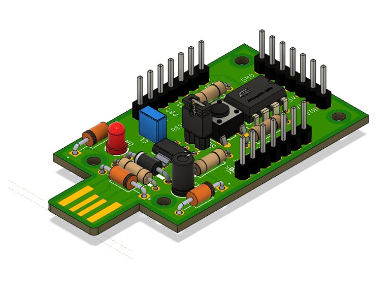
Its creation was inspired by the circuit of the Digispark circuit board. Below, we present the board that we have developed for you. See Figure 1.
Figure 1 - Mini ATTINY85.
We analyzed the Digispark circuit and introduced some modifications. The purpose is to add new features and functionality to the board.
What will you learn in this article?
- Understand the structure of the ATTINY85 Microcontroller;
- Understand the purpose of each component of the development board circuit with the ATTINY85 Microcontroller;
- How and why it is important to use digital prototyping software to create electronic designs;
- Analyze the main functionalities of the electronic board.
Now, let's introduce the complete project of the Mini Attiny85 Board.
How did the idea to develop the Attiny85 board come about?The circuit of this board was inspired by the electronic schematic of the DigisPark development board, which uses the ATTINY85 Microcontroller.
Figure 2 shows the Digispark board and its pins.
These are all the features present in the ATTINY85 Microcontroller.
- Digital input and output pins;
- Analog-digital converter;
- PWM;
- I2C;
- IPS;
- External Interrupt.
ATTINY85 is small but powerful for building countless solutions. Next, we will present the electronic schematic of the board and how the circuit works. Shall we travel in electronics?
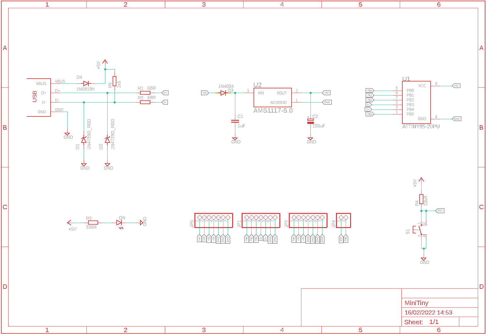
How does the board circuit work with the Attiny85 Microcontroller?In the figure below we have the complete schematic of the electronic circuit of our board.
We'll start the discussion with the board's power circuit. See the figure below.
Next, we will explain how this circuit works.
The Arduino ATTINY85 board power circuitThe circuit on the board is designed to be powered with a voltage between 7V and 12V.
This external supply voltage must be applied to the Vin and GND pins.
Note that the input voltage (Vin) will arrive at the 1N4004 diode.
This diode is used to protect the attiny85 microcontroller circuit against reverse polarity of the power supply.
Couldn't understand?
Imagine that you accidentally reversed your power supply terminals. Put GND on Vin and Vin on GND.
Do you agree that this is a polarity reversal of your power supply?
Therefore, this diode will protect the circuit. Remember: the rectifier diode only conducts in one direction. That way, your circuit will not conduct and you will protect it against this failure.
The diode causes a voltage drop of 0.7V in the value of the input voltage Vin). This is because of the characteristics (barrier potential) of the silicon rectifier diode.
The AMS1117-5V voltage regulatorThen this voltage arrives at the input of the AMS1117-5V voltage regulator. Now, I need you to pay attention to this: the ATTINY85 microcontroller operates with a voltage of 5V. That's why we use this regulator. It will offer a regulated voltage of 5V to the CHIP.
The capacitors shown in the circuit are recommended by the AMS1117-5V datasheet.
The 5V voltage is distributed to different parts of the circuit.
Energized board indication circuitIn several equipments we find a circuit with LED to indicate its on/off state. The circuit below has this function.
The LED is activated when the board is powered up. The 330R resistor has the function of limiting the LED current.
Code transfer circuit for the ATTINY85 MicrocontrollerThe circuit below is responsible for transferring the program code to the ATTINY85 microcontroller.
USB has 4 terminals. There are 2 for power supply (VBUS and GND) and 2 for data transfer (D+ and D-). Diodes D1 and D2 are of the Zener type. They limit the voltage of the data lines to 3.6V.
What is the purpose of Diode D4?
Diode D4 is used to ensure the protection of various elements of your circuit. I will explain in more detail.
This diode is to prevent USB transients or overvoltages from damaging the ATTINY85 microcontroller and various other components.
Next, we will talk about the button that was used for two purposes: reset and general purpose.
Reset button and general purposeIn most applications we find a reset button. It is useful when you want to reset the application, in case there is a problem executing the code.
The ATTINY85 microcontroller has few digital pins and it is not interesting to leave it with an exclusive pin for the reset button.
How to make this pin be used as digital and have the possibility to disconnect it from the reset function? For this situation we use a jumper. See the figure below.
The JP4 jumper has the function of connecting and disconnecting the circuit from the button to the RESET pin (PB5). So, you can do two things:
Use the PB5 pin as digital in an application;
Connect a wire to the jumper connection and use the button on another pin as a digital input.
Next you'll see the printed circuit board layout of the project.
Printed Circuit Board Layout and 3D PrototypeWe developed the circuit board layout with the help of Autodesk Eagle Software. Below you can see the result. The length and width of the board is 59×31 cm, respectively.
I want you to notice something interesting. On most Arduino boards we have a maximum of 2 to 3 GND pins. This low amount forces the user to make connections between the wires. This often leads to a bad contact problem.
To avoid this, we added extra GND, VCC and Vin pins. In this way, you can easily assemble your connections in a simple and headache-free way.
See the final result of the 3D printed circuit board in the figure below.
Now you can enjoy and win 10 free PCBWay units.Go to the website, create your account and earn right now.
Final DiscussionsIn the next article we will teach you how to prepare the Arduino ATTINY to receive the code and we will develop an example application.


_t9PF3orMPd.png?auto=compress%2Cformat&w=40&h=40&fit=fillmax&bg=fff&dpr=2)


Comments
Please log in or sign up to comment.