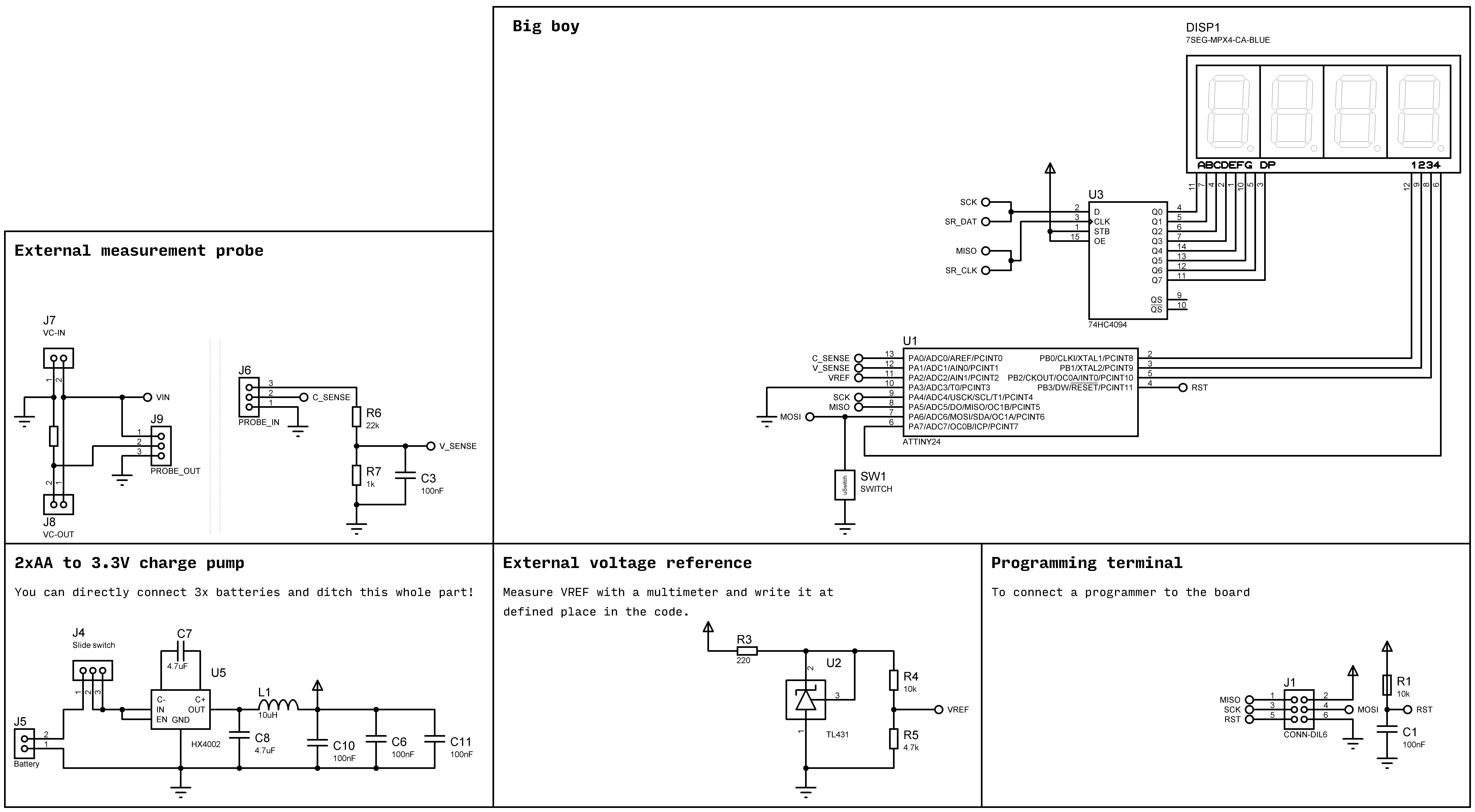
I usually had problems when I wanted to measure supply voltage and current consumption of a circuit using multi-meters. They can measure either voltage, or current and can't measure them simultaneously; You have to change probe terminal and the selector to measure each one at a time. That's the idea behind this device.
ATtiny microcontrollers are usually used in little projects where the demands on memory or pin count is low. So their other capabilities are usually overlooked.
ATtinys' capable ADC:They [not all of them] have a very capable ADC with 20x gain, differential inputs with uni-polar or bi-polar measurements and a 1.1V reference. You can use them to measure very tiny signals like thermocouples or RTD sensors.
I used an ATtiny24A for this project. as the internal 1.1V reference has a big error, I used a 2.5V voltage reference with a 1/3 divider to provide 0.8V reference for it. you have to measure the VREF on the PCB with a multimeter and write down the value in the defined part of code in milli-volts, e.g. 806.
The features:- It's Self powered; it doesn't use the measured circuit's supply. so it can measure tiny voltages like 10mV
- The main board has a header input. you can design any probe with that same 3 pins layout to best suit your case
- It automatically changes the range to show the value with best precision
- The code uses 54 bytes out of 128 bytes of RAM on ATtiny24A, and 1234 bytes out of 2048 bytes of flash. there is a lot of room if you are going to make it better.
Using the onboard push-button you can switch between these values:
- The calculated internal voltage reference (you should read something very near to 1100. my device shows 1084)
- The voltage of the probe. It automatically switches the "dot" point to show 2 digit voltages. (0.000 to 00.00)
- The current flowing through the probe. It automatically switches the "dot" point to show 2 digit currents. (0.000 to 00.00)
- The VREF:measure the VREF on the PCB with a multimeter and write down the value in the defined part of code in milli-volts, e.g. 806.
- The Divider value:Measure the resistor divider ratio and write it down. as the resistors have errors, measure R6 and R7 with a multimeter, calculate R6/(R6+R7), multiply it by 10 and write it down.
- The Shunt resistor value:Measure the shunt resistor with a multimeter and write it in milli-ohms


Comments
Please log in or sign up to comment.