Nelson LomickCarson DrakePeyton Freeman
Published

Audio monitoring system

A new way to monitor a speaker during extended break-in use. Notifies the owner if the woofer exhibits negative characteristics.

IntermediateWork in progress116
Audio monitoring system

Things used in this project

Hardware components

Argon
Particle Argon
×3
Flying Fish MH sensor
×1
GY Max4466 microphone
×1
AIS Touch Sensor
https://www.digikey.com/en/products/detail/omron-electronics-inc-emc-div/B3F-1020/44059?utm_adgroup=Essen%20Deinki&utm_source=google&utm_medium=cpc&utm_campaign=Shopping_DK%2BSupplier_Other&utm_term=&utm_content=Essen%20Deinki&gclid=Cj0KCQjw0umSBhDrARIsAH7FCoeVOBHESa0ZNd5D47bLw024OdiqvBu_41NGlSmY2Ytv2AHapxbsehoaAhZjEALw_wcB
×1
Solderless Breadboard Half Size
×3
LED (generic)
LED (generic)
×2
Resistor Kit, 50-Pieces each
×1

Software apps and online services

Particle Build Web IDE
Maker service
IFTTT Maker service

Story

Read more

Custom parts and enclosures

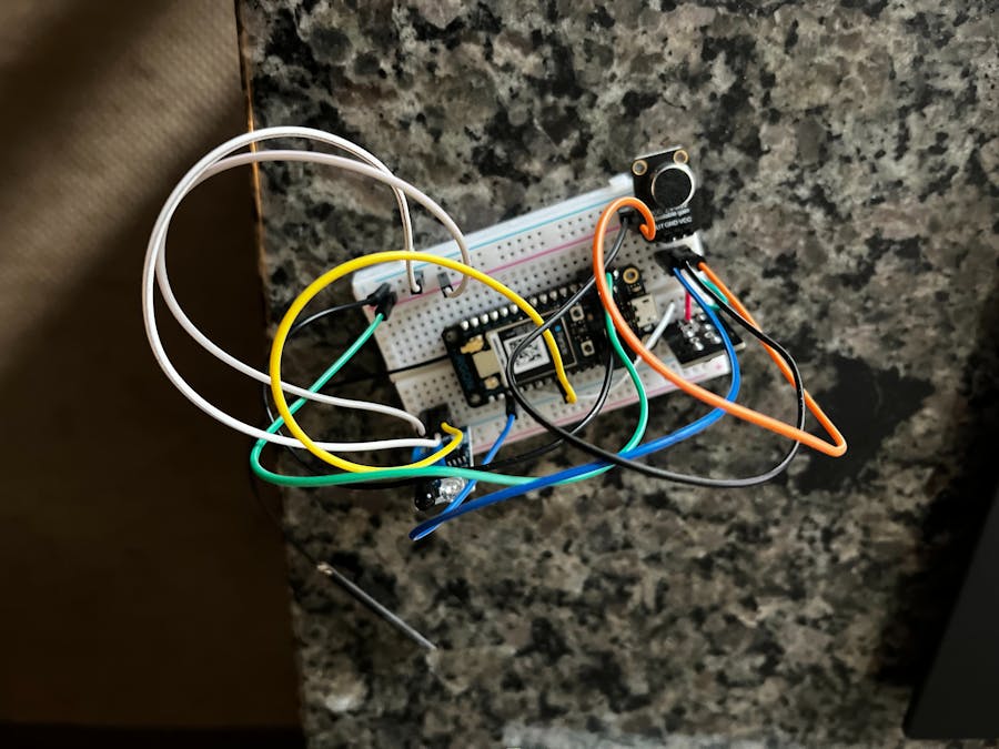
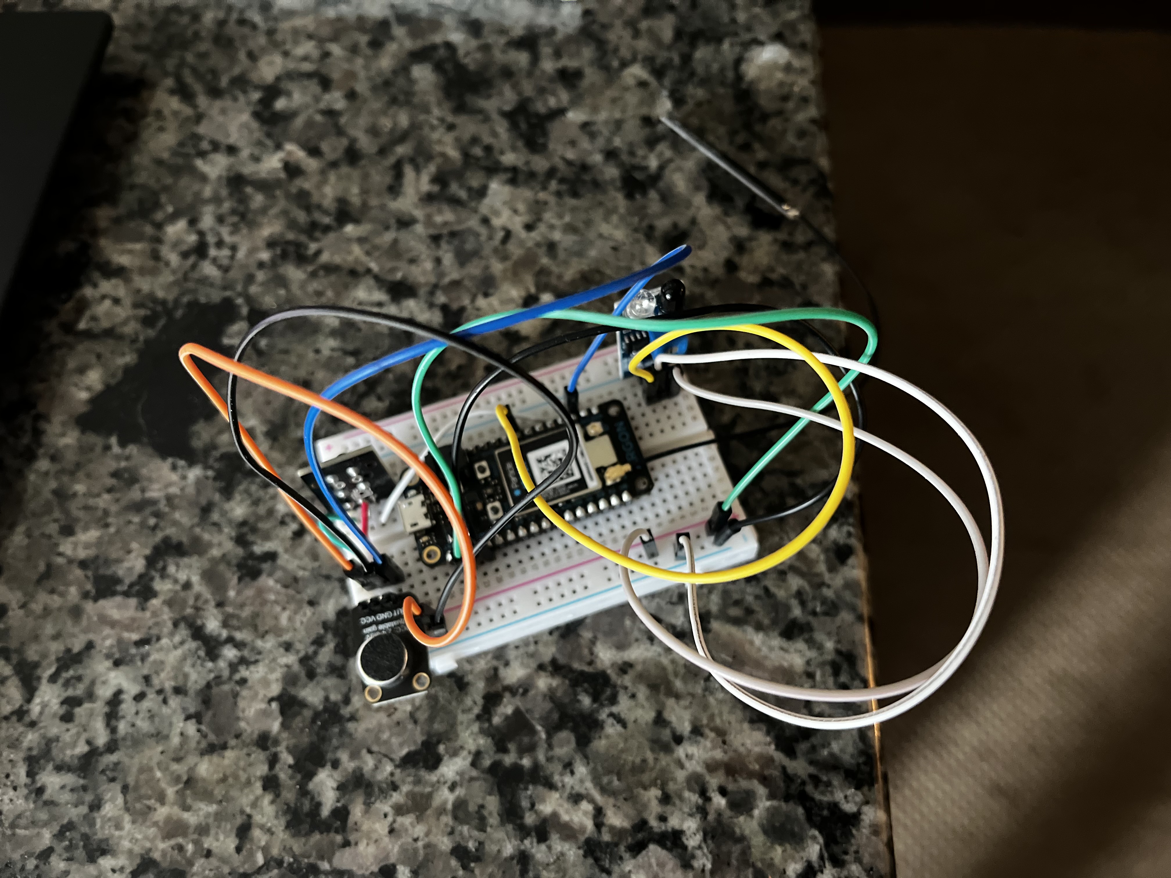
Carson's Argon setup

This setup uses three sensors, one to ensure proper connection between boards (the button) and two sensors to monitor the speaker.

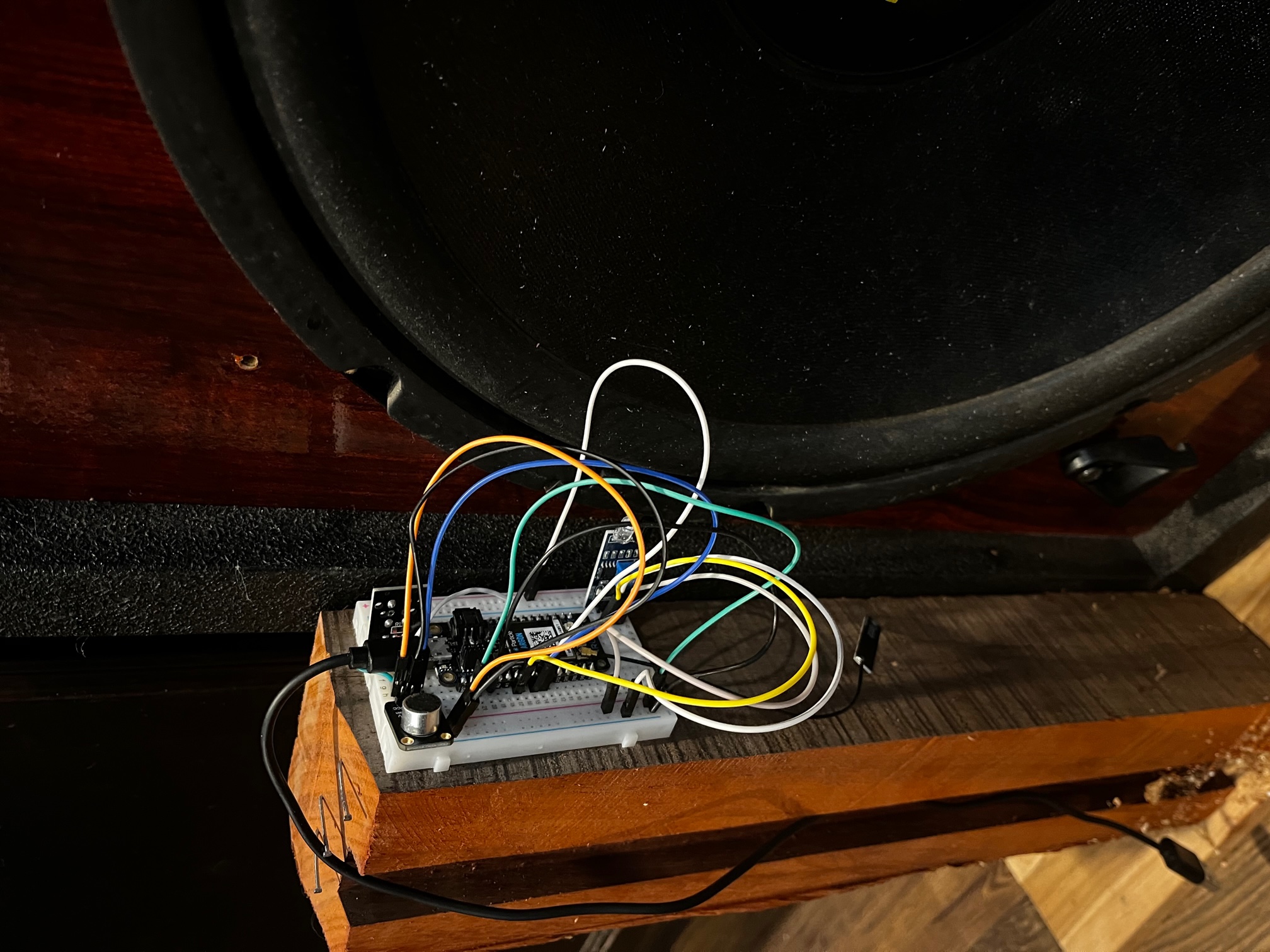
Speaker monitor

Board used to monitor the speaker

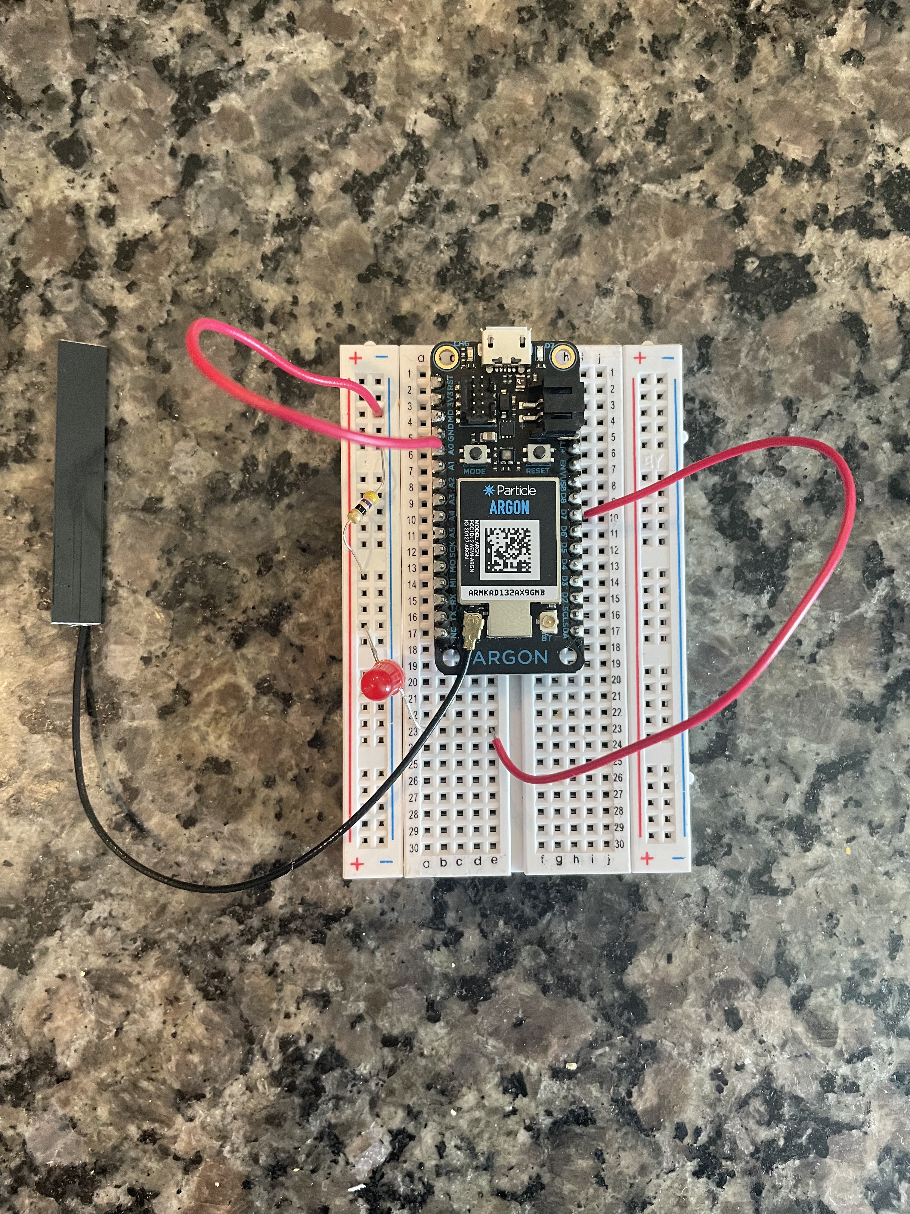
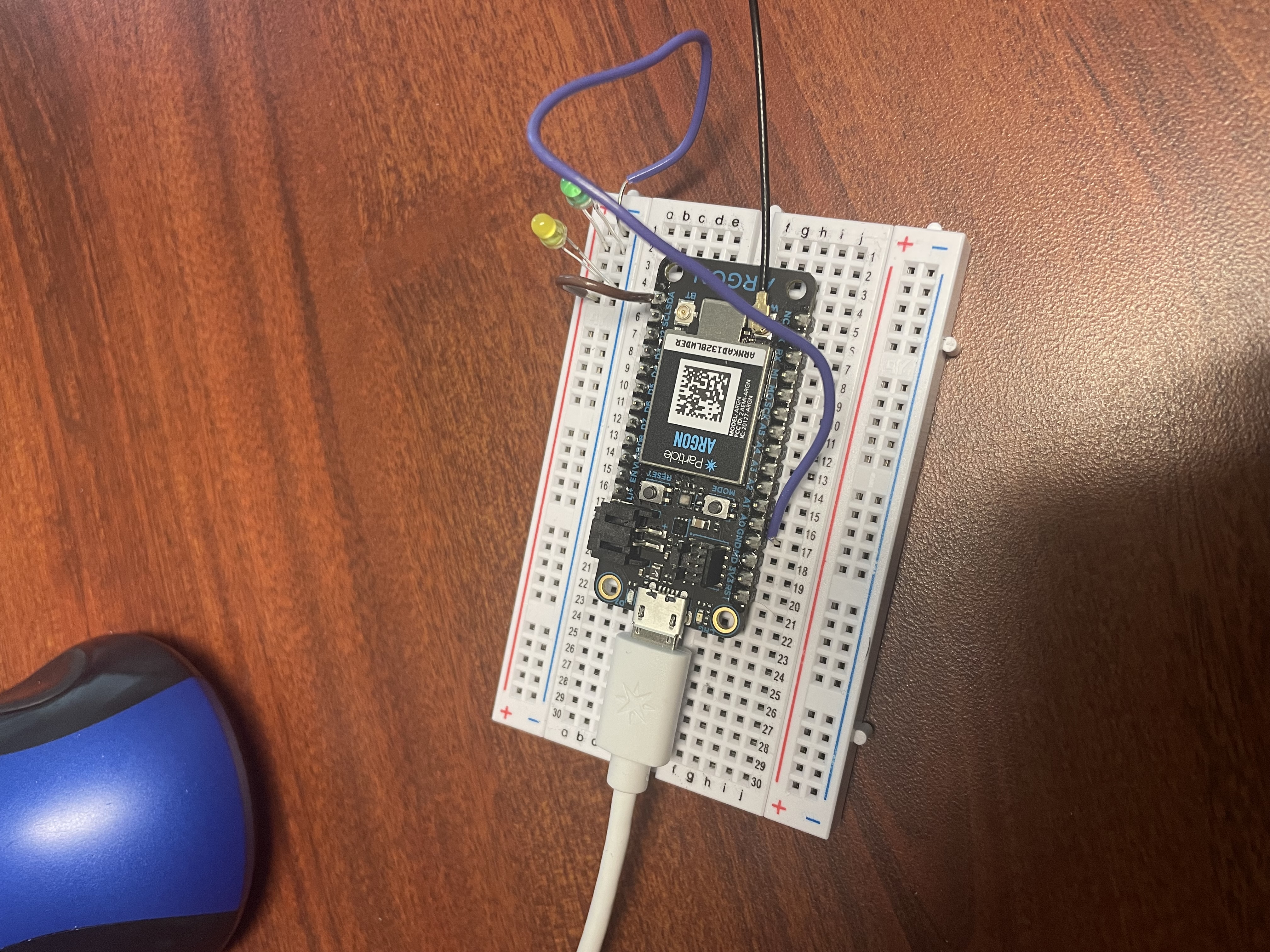
Peytons receiving Argon Board

The light turns on when the button is pressed or the sensors exceed parameters to indicate a problem.

Nelson recieving argon setup

The light turns on when the button is pressed or parameters for the sensors exceed a specific value.

Schematics

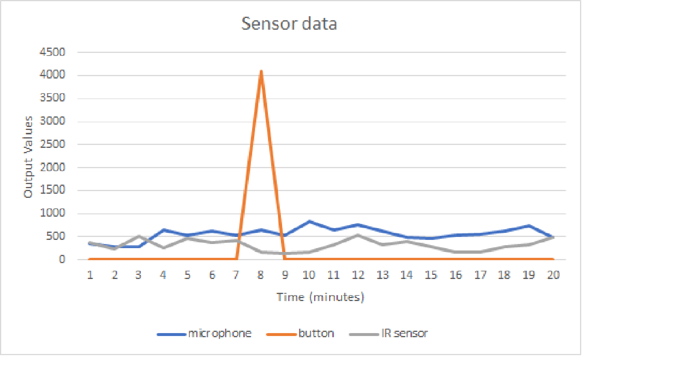
Sensor readouts

Value of each sensor taken every minute for twenty minutes. Button was activated for one point to show functionality of button read out. These values were measured with varying volume levels, and then using the maximum values parameters were set for the monitoring.

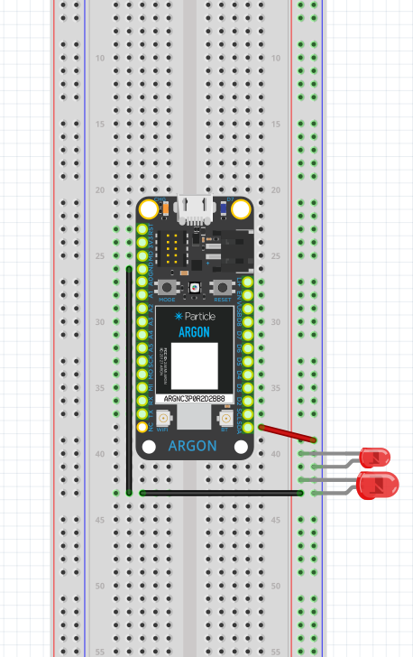
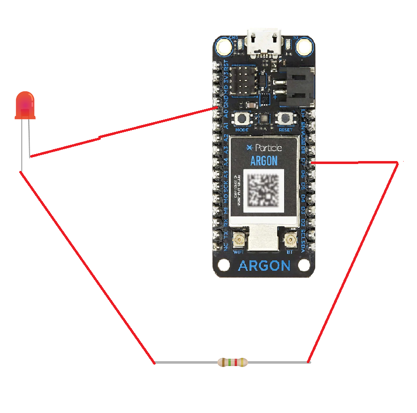
Nelson's Schematic for Argon setup

Setup for Nelsons receiving Argon board.

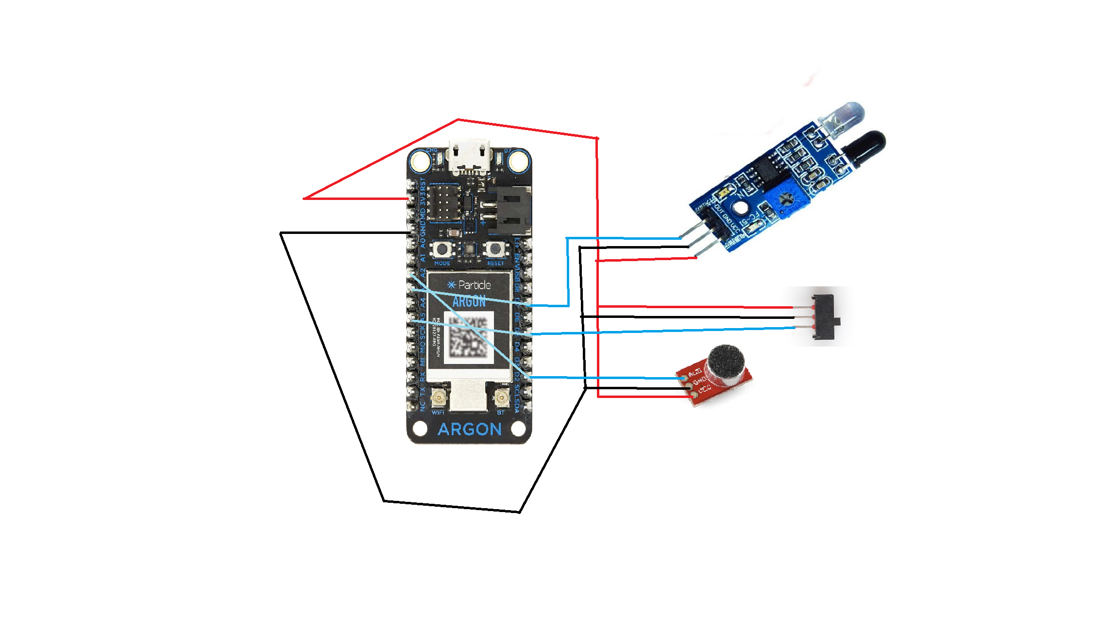
Monitoring argon board schematic

Simply push the button to ensure proper connection between argon boards. All outputs are sent to the analog side of the Argon board and thus were capable of sending a wide range of values.

Recieving Argon Board Schematic

When IFTTT is triggered due to sensor reading outside of the set parameter it causes this board to run a code causing the led to turn on.

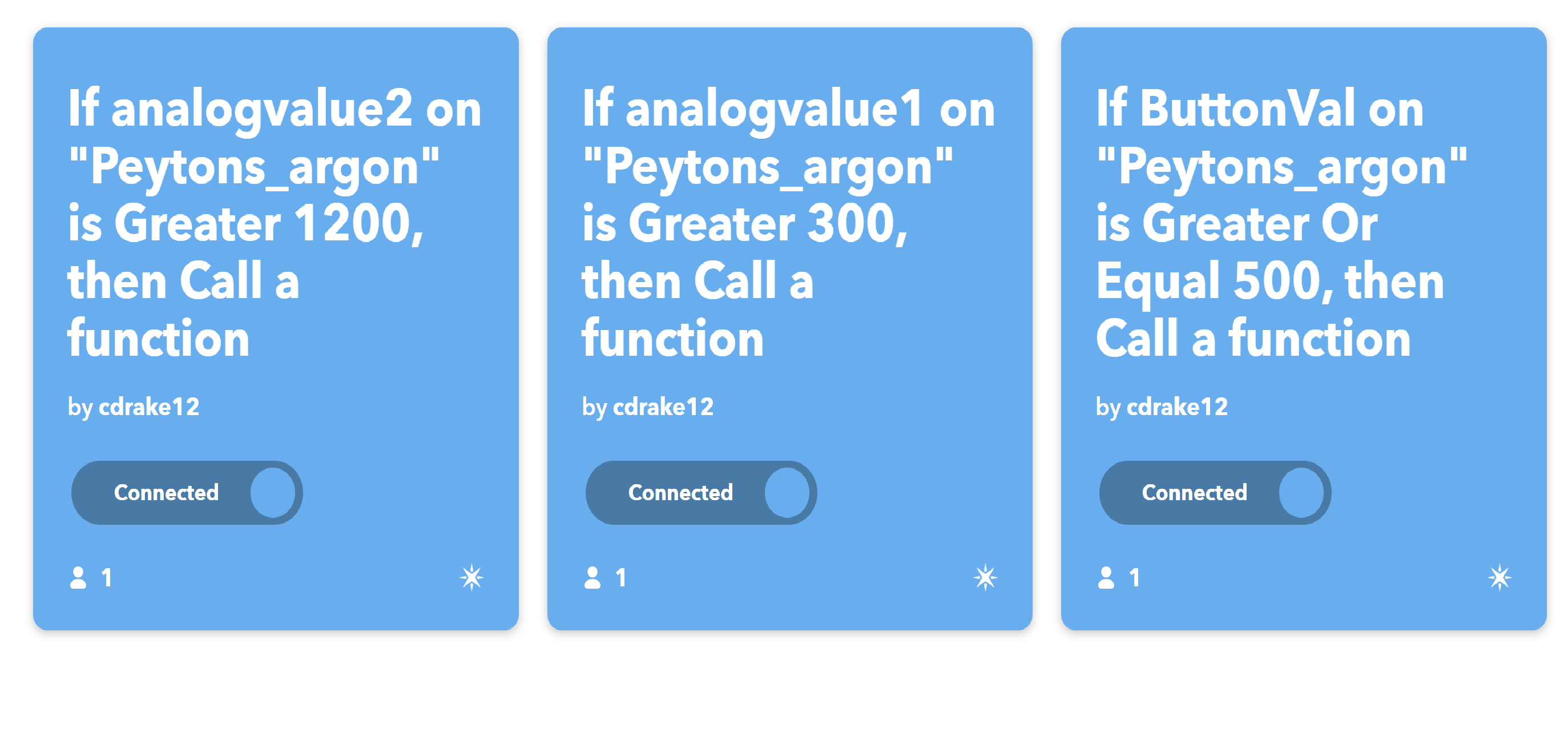
IFTTT parameters for sensors

This details the IFTTT usage which allowed communication between Argon boards. Note "Peyton's Argon" and "Carson's Argon" are flipped in IFTTT compared to the rest of the project as there were issues with power coming from "Carsons Argon", and the boards had to have sensors switched between them. Analog value 1 is the IR sensor and Analog value 2 is the microphone.

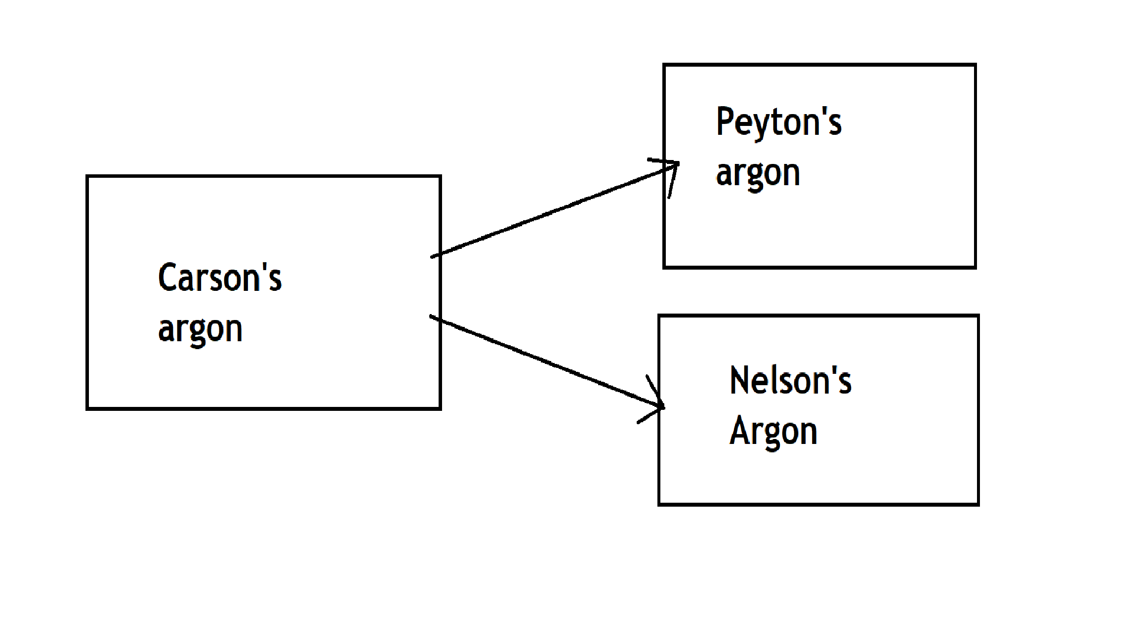
Flowchart

This flowchart details the flow of information between Argons. Currently there is only one argon board monitoring, however in the future two will likely be used so as to monitor a pair of speakers at the same time.

Code

Code for receiving Argon boards

C/C++
LED lights must be inserted in D0 and D7 of the particle argon. Also, being connected to the ground as well to light.
int led1 = D0;
int led2 = D7;

// Last time, we only needed to declare pins in the setup function.
// This time, we are also going to register our Particle function

void setup()
{

   // Here's the pin configuration, same as last time
   pinMode(led1, OUTPUT);
   pinMode(led2, OUTPUT);

   // We are also going to declare a Particle.function so that we can turn the LED on and off from the cloud.
   Particle.function("led",ledToggle);
   // This is saying that when we ask the cloud for the function "led", it will employ the function ledToggle() from this app.

   // For good measure, let's also make sure both LEDs are off when we start:
   digitalWrite(led1, LOW);
   digitalWrite(led2, LOW);

}


// Last time, we wanted to continously blink the LED on and off
// Since we're waiting for input through the cloud this time,
// we don't actually need to put anything in the loop

void loop()
{
   // Nothing to do here
}

// We're going to have a super cool function now that gets called when a matching API request is sent
// This is the ledToggle function we registered to the "led" Particle.function earlier.


int ledToggle(String command) {
    /* Particle.functions always take a string as an argument and return an integer.
    Since we can pass a string, it means that we can give the program commands on how the function should be used.
    In this case, telling the function "on" will turn the LED on and telling it "off" will turn the LED off.
    Then, the function returns a value to us to let us know what happened.
    In this case, it will return 1 for the LEDs turning on, 0 for the LEDs turning off,
    and -1 if we received a totally bogus command that didn't do anything to the LEDs.
    */

    if (command=="on") {
        digitalWrite(led1,HIGH);
        digitalWrite(led2,HIGH);
        return 1;
    }
    else if (command=="off") {
        digitalWrite(led1,LOW);
        digitalWrite(led2,LOW);
        return 0;
    }
    else {
        return -1;
    }
}

Monitoring Argon Board

C/C++
Monitors the speakers using a microphone and IR sensor. All sensors are monitored using the analog inputs on the Argon board.
 // This is where your LED is plugged in. The other side goes to a resistor connected to GND.
int button = A5;
int photoresistor = A2;
int Microphone = A3;// This is where your photoresistor is plugged in. The other side goes to the "power" pin (below).

int analogvalue1;
int analogvalue2;// Here we are declaring the integer variable analogvalue, which we will use later to store the value of the photoresistor.
int buttonVal;

// Next we go into the setup function.

void setup() {

    // First, declare all of our pins. This lets our device know which ones will be used for outputting voltage, and which ones will read incoming voltage.
    // Our LED pin is output (lighting up the LED)
    pinMode(photoresistor,INPUT);
    pinMode(Microphone,INPUT);
    pinMode(button, INPUT_PULLDOWN); 
    // Our photoresistor pin is input (reading the photoresistor)
    // The pin powering the photoresistor is output (sending out consistent power)

    // Next, write the power of the photoresistor to be the maximum possible, so that we can use this for power.
  Particle.variable("analogvalue1", &analogvalue1, INT);
Particle.variable("analogvalue2", &analogvalue2, INT);
Particle.variable("ButtonVal",&buttonVal, INT);
    ;
    
}


void loop() {

    // check to see what the value of the photoresistor is and store it in the int variable analogvalue
    analogvalue1 = analogRead(photoresistor);
    analogvalue2 = analogRead(Microphone);
     buttonVal = analogRead(button);
 

}


// Finally, we will write out our ledToggle function, which is referenced by the Particle.function() called "led"

Credits

Nelson Lomick

Nelson Lomick

1 project • 0 followers
Carson Drake

Carson Drake

0 projects • 2 followers
Peyton Freeman

Peyton Freeman

0 projects • 1 follower

Comments