One of the advantages of the Arduino 101 is it's onboard BLE capability and easy to use CurieBLE library. However, there are some limitations to BLE distance of transmission and data rate transmission. BLE is great for short range, low bandwidth transmissions. Think of the connection between smartwatches and smartphones. However this is limited to about 30 feet or so. It is also good for reliable data transmission, but unlike traditional Bluetooth it is not an ideal solution for rapid data transmission. I learned this when I first began experimenting with BLE last year, I made a small demo to share real time clock data from an Arduino 101 to a hybrid mobile web app, and always found a consistent 2-3 second delay in times between the Arduino 101 and the app!
In preparation for a new project where we would like to have rapid, wireless transmission in the field at distances much greater than 30 feet, we began experimenting with some packet radio breakout boards.
The things we learned began to add up, so instead of writing it all up at the end, we thought it would be better to present this as an informal "Part 1" detailing getting packet radio up and running on the Arduino 101.
Not LoRaNote this is NOT a LoRa packet radio project. After doing some reading and watching some videos about LoRa we were concerned that despite the much great range of transmission, the project might suffer from lower data rates of LoRa. LoRa breakout boards are also generally more expensive, but this wasn't as big a concern.
Packet RadioWhat exactly is packet radio? What's the difference between RFM69 and LoRa? I recommend checking out the fine resources listed here:
For this tutorial, I will focus on getting the Adafruit RFM69HCW transceiver up and running with an Arduino 101 or TinyTILE.
The ProjectThis project will demonstrate how to use the Adafruit RFM69HCW Transceiver Radio Breakout - 868 or 915 MHz(PRODUCT ID: 3070) to transmit IMU data from one Arduino 101 or TinyTILE to another.
We will modify the IMU Orientation Visualizer sketch to show the orientation of the transmitting Arduino 101. The Orientation Visualizer example was one of the reasons we got interested in using the Arduino 101 in the first place. We are going to assume you can get both the Arduino IDE up and running for the Arduino 101 and that you can also get processing up and running.
APIThe Packet Radio API: The two major packet radio libraries available to use for Arduino:
This is great. They are well documented and contain numerous examples to learn from. However when I first tried to compile each for the Arduino 101 in the Arduino IDE "out-of-the-box", they both bombed out!
ChallengesThis has happened to me before. Many of the APIs available for Arduino have been optimized for the specific chip/architecture of the Arduino. The Arduino 101, however, using an entirely different microcontroller. So software optimized for the AVR using things such as chip specific registers, timers, etc. will not function on the Arduino 101. These programs are trying to utilize things that do not exist on the Arduino 101! For those not expert in embedded programming, working through the documentation, code, datasheets is a daunting, if not project killing, task.
GoogleSo I did what I do when this has happened to me in the past: I googled it! A quick google search showed that Sparkfun has a similar board and user Hartatak62 ran into the same problem with another type and provided some code that should run generically in the Arduino IDE! Problem thankfully solved by the Maker community! The Sparkfun library, RFM69HCW_Breakout, is at available on GitHub.
But as Hartatak62 notes, there are a few things you need to do before this modified library will work with the Arduino 101. We also came up with a few other gotchas, all of these are listed below:
Importing the Modified Library- Download the Sparkfun library from their Github site and a .zip file.
- In the Arduino IDE, go to the Sketch tab and select Include Library and then select Add .ZIP library.
- Find the library and add it!
We're not ready to use the library just yet. According to Hartatak62, two modifications were needed to make this library work on the Arduino 101.
First ChangeThe 101 to transmit through the RFM69HCW works! It still won't receive, but I edited the RFM69.cpp file in the RFM69 library to change SPI.setClockDivider(SPI_CLOCK_DIV2); to SPI.setClockDivider(SPI_CLOCK_DIV8);. This slows down the SPI clock significantly (half the processor clock speed slowed down to 1/8 the processor clock speed), allowing the RFM69 to understand the SPI communication.
So let's go and do this. Find the library you added to your Arduino IDE environment, my was located in:
C:\Users\greg\Documents\Arduino\libraries\RFM69
Open the file, RFM69.cpp your editor of choice, mine is atom, and make the change (line 451 in atom).
 // set RFM69 SPI settings
 SPI.setDataMode(SPI_MODE0);
 SPI.setBitOrder(MSBFIRST);
 SPI.setClockDivider(SPI_CLOCK_DIV8); // decided to slow down from DIV2 after SPI stalling in some instances, especially visible on mega1284p when RFM69 and FLASH chip both present
 digitalWrite(_slaveSelectPin, LOW);
After more research I finally figured out why I could transmit, but not receive. The radios were outputting an interrupt signal that wasn't being received by the 101. As it turns out, Arduino changed the Interrupt numbers to match the Interrupt pins on "new boards with high performances processors," starting with the Arduino Due. The RFM69 Library hasn't been updated to work this way. It's set to use Interrupt Number 0, which it expects to be on pin 2. But now Interrupt Number 0 is on pin 0, and Interrupt 2 is on pin 2. So I edited RFM69.h to change the Interrupt Number to the Interrupt Pin (since I'll be using pin 2). _interruptNum = interruptNum; which is now _interruptNum = interruptPin.
Open the file, RFM69.h your editor of choice, mine is atom, and make the change (line 96 in atom).
RFM69(uint8_t slaveSelectPin=RF69_SPI_CS, uint8_t interruptPin=RF69_IRQ_PIN, bool isRFM69HW=false, uint8_t interruptNum=RF69_IRQ_NUM) {
     _slaveSelectPin = slaveSelectPin;
     _interruptPin = interruptPin;
     _interruptNum = interruptPin;
     _mode = RF69_MODE_STANDBY;
     _promiscuousMode = false;
     _powerLevel = 31;
     _isRFM69HW = isRFM69HW;
   }
You can now use this library in your sketches:
#include <RFM69.h>
The reason this modified library works , in addition to the changes by Haratak62, is that the contributor has eliminated something called an "ATOMIC BLOCK" which is something similar to disabling interrupts. This is not available, or at least the keyword is not recognized by the Curie chip. If you use the Arduino 101( or TinyTILE), this will happen as sometimes programmers take advantage of microcontroller specific features to optimize their code. This makes in non-portable to another microcontroller. Luckily, this has been corrected for this breakout board. Even better in this case, the code works for the Adafruit breakout board! There is one more catch, which will be covered below.
Probably the best part of all if this, is that in a message exchange about an unrelated project, fellow Hackster.io member, Darian Johnson and I, were able to share this information! His questions greatly helped me clarify this write-up So remember, when you overcome a problem, write it up and share it! I think there is no greater way to give back to our fellow makers!
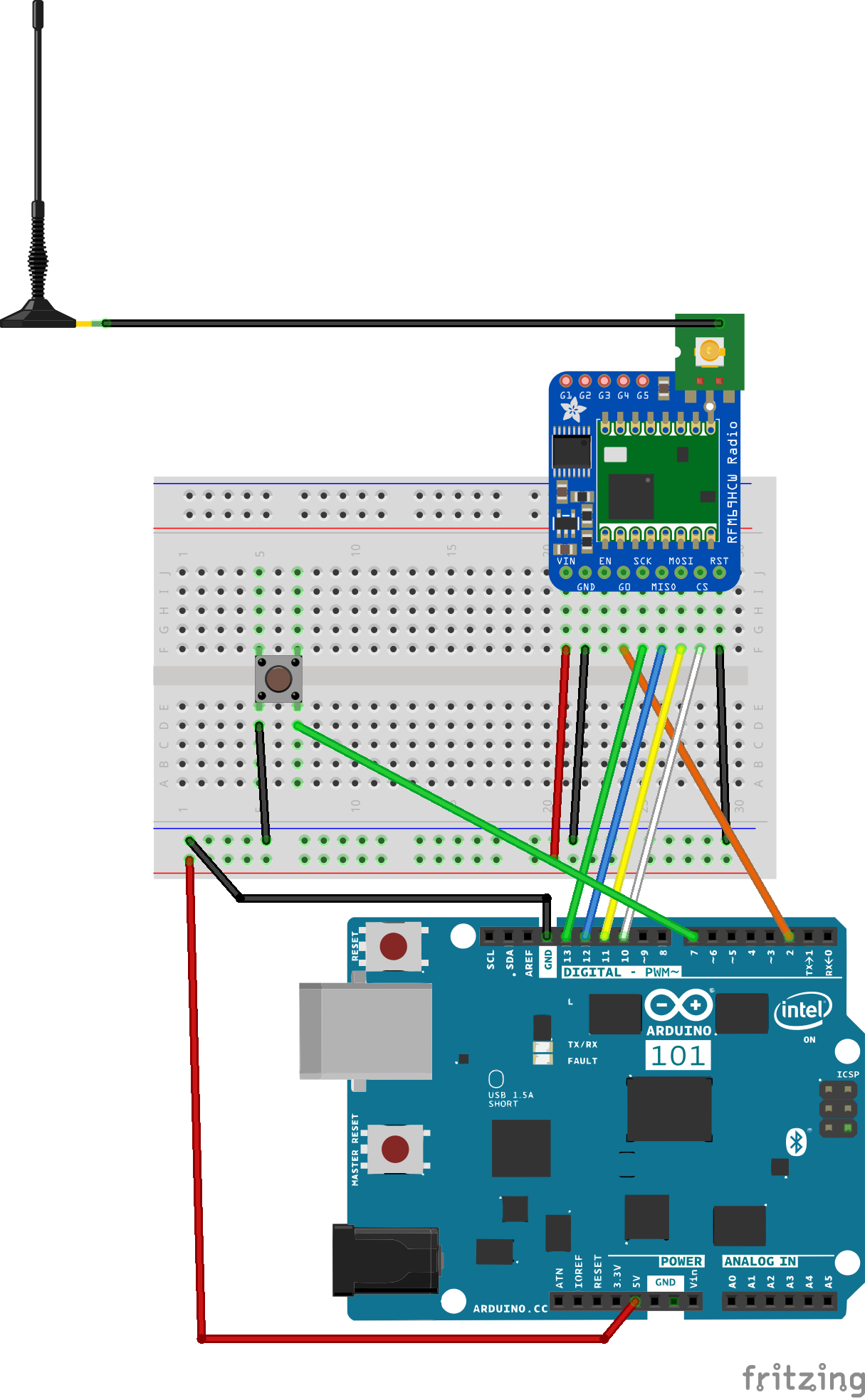
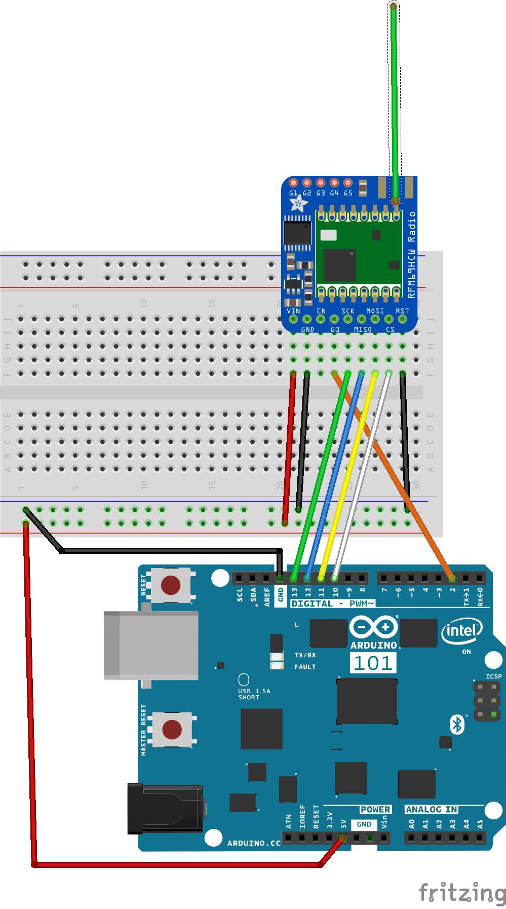
Wiring the BoardWe're almost there...after installing the library, and making the necessary changes to the code, then wiring up the breakout board, the circuits still did not work! After comparing the circuit diagrams on the Adafruit and SparkFun tutorials, we noticed that the RESET pin on the Adafruit circuit was connected to pin 2 on the Arduino. The SparkFun board, however, does not use this pin. Making a lucky guess, we simply attached this pin to ground, and viola...it worked!
This is demonstrated in the pictures below and Fritzing diagrams below.
The green button in the circuit above is used to tell the TinyTILE or IMU half of the pair when to start and stop data transmission. The antenna is used on this end of circuit in hopes that it will help increase the distance of the reception of the combined circuits. The antenna will be too heavy for the final application on the IMU transmitting side, however.
Bench TestingIt is a little bit like magic when the data starts to come across! I recommend that after making each circuit you test them using the example sketch provided with the SparkFun modified RFM69 library, SFE_RFM69HCW_example.ino, before using the receiver01.ino and transmitter01.ino files in my Github repository. This example sketch is simpler to understand and will help you debug your wiring, etc.
In order to work with the example sketch, you will need to open a separate instance of the Arduino IDE for each transceiver and make sure you know which Arduino 101/TinyTILE is which in terms of Ports!
Unique Node ID'sAlso, it is very important to note that these transceiver are made for multi-node or multi-transceiver networks. The example sketch, as a single sketch, assigns the same node ID or number to the nodes. So in addition to keeping track of which circuit is attached to which port in which Arduino IDE, you will also need to modify each sketch to make the node ID's unique:
// Addresses for this node. CHANGE THESE FOR EACH NODE!
#define NETWORKID     0   // Must be the same for all nodes (0 to 255)
#define MYNODEID      1   // My node ID (0 to 255)
#define TONODEID      2   // Destination node ID (0 to 254, 255 = broadcast)
For the other node, this should be changed to something like:
// Addresses for this node. CHANGE THESE FOR EACH NODE!
#define NETWORKID     0   // Must be the same for all nodes (0 to 255)
#define MYNODEID      2  // My node ID (0 to 255)
#define TONODEID      1   // Destination node ID (0 to 254, 255 = broadcast)
In the sketches, receiver01.ino and transmitter01.ino in my Github repository, this change has already been made.
Orientation VisualizerOnce you have made sure your circuits are working, you can move on to working with the Arduino 101 Orientation Visualizer example.
- Download the receiver01.ino sketch onto one of your boards and attach this to your computer that has Processing and the Arduino 101 Orientation Visualizer processing code setup to run on it.
- Separately, download the transmitter01.ino sketch to another board, in our case a TinyTILE. We attached a battery to this circuit for power and did not attach it to the same computer running Processing.
- I pressed the reset button on each circuit and waited for about 5 seconds. Then I started up the processing sketch. After seeing the graphic of the Arduino 101 show up, press the button to start data transmission. You should the board orientation change immediately in response to changes in position of the transmitter board!
This all works fine on the bench with a few inches to a few feet of separation, but what about in the field?
Power supply! A disturbing phenomenon occurred when we were testing the circuits. Occasionally and unpredictably it appeared that the graphical representation of the Arduino 101 board would get locked in a continuous rotation. The only way to correct this was to restart both halves of the circuit. Phil V. noticed that this also happened when one of the power supply wires would become dislodged from the transmitter end of the circuit. What we concluded from trying different power supplies, was that weak or dying batteries would cause this to happen. Why, not exactly sure, but it did not occur with strong or fully charged batteries, or a direct connection to a laptop.
Hope you enjoy this project and hope that it helps you get started with packet radio on your Arduino 101 or TinyTILE!


_baVEVgguW1.jpg?auto=compress%2Cformat&w=48&h=48&fit=fill&bg=ffffff)


Comments
Please log in or sign up to comment.