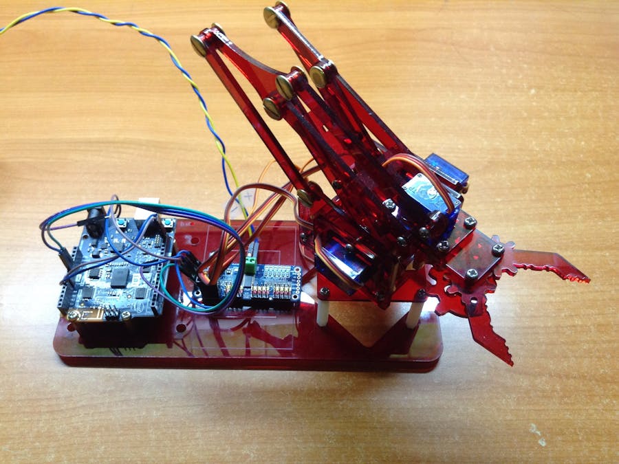
This topic will introduce a popular education robot arm - MeArm with Arduino 101. And build Android app with MIT App Inventor to control it.
Arduino 101 is the co-branded board by Arduino and Intel and was announced at Rome Maker Faire 2015. This $30 USD board is powered by the Intel Curie module, along with a 6-axis accelerometer with a gyroscope, and capability for Bluetooth Low Energy (BLE). Arduino 101’s pin layout and I/O capabilities are almost identical compared with Arduino UNO.
Please download Arduino 1.6.x or later version. The latest version is 1.8.3 but versions after 1.6.x works just fine.
Download and extract, and double click arduino.exe to launch Arduino IDE.
Next step is to download Arduino 101’s package (driver included). Please open Boards Manager from Tools -> Board -> Boards Manager, then search ”101” keyword. There should be a result of “Intel Curie Boards by Intel”. Select the latest version and click “Install”.
For Windows user, there will be several prompt asking whether you would like to install Arduino 101, please click yes to all prompt or your PC may not able to recognize Arduino 101 properly.
This project uses an Adafruit PCA9685 16-channel servo controller, it can control max for 16 servos through I2C interface. Although you can control servo directly from your Arduino’s PWM pins, we suggest to use additional board to control for protection and better performance.
Please download Adafruit-PWM-Servo-Driver-Library from Adafruit’s github page. Click Clone or download / Download ZIP at the top-right corner of this webpage.
Here need no extraction, please import this library from Arduino IDE / Sketch / Include Library / Add .ZIP Library. It will be added into Arduino IDE/libraries folder.
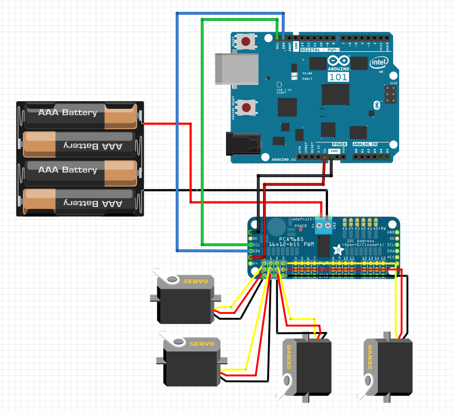
- Servo to PCA9685: Please connect four servos to PCA9685 board’s 3-pin port #0~#3, beware not to connect in wrong direction!
- Battery to PCA9685: Connect your battery holder's red/black wire to PCA9685’s +/- power terminal. When you try to control multiple actuator like servo, DC motor, it is very important to support them by separate power supply in case of insufficient current. This may cause Arduino 101 to be malfunctioned or damaged.
- PCA9685 to Arduino 101: As for I2C interface, please connect its SCL/SDA pins to Arduino 101’ SCL/SDA pins separately.
- Arduino 101’s power supply: Please connect PCA9685’s V+/GND to Arduino 101’s 5V/GND pin. Your Arduino 101 will use power from PCA9685 to start working. Finish.
Your project will look like figure below, another advantage of using PCA9685 is that we can get rid of breadboard and disorderly wires. Enjoy!
Open a new Arduino sketch and paste code below. Check you’ve select Arduino/Genuino 101 and the correct COM port, then upload this sketch.
#include <CurieBLE.h>
#include <Wire.h>
#include <Adafruit_PWMServoDriver.h>
#define SERVOMIN  150
#define SERVOMAX  600
Adafruit_PWMServoDriver pwm = Adafruit_PWMServoDriver();
BLEService BLE_serv("19B10010-E8F2-537E-4F6C-D104768A1214");
BLEUnsignedIntCharacteristic BLE_char("19B10011-E8F2-537E-4F6C-D104768A1214", BLERead | BLEWrite);
void setup()
{
   Serial.begin(9600);
   pwm.begin();
   pwm.setPWMFreq(60);
   BLE.begin();
   BLE.setLocalName("mearm");
   BLE.setAdvertisedService(BLE_serv);
   BLE_serv.addCharacteristic(BLE_char);
   BLE.addService(BLE_serv);
   BLE_char.setValue(0);
   BLE.advertise();
   Serial.println("Waiting for connections...");
}
void loop() {
   BLEDevice central = BLE.central();
   if(central)
   {
       Serial.print("Connected to central");
       Serial.println(central.address());
       while(central.connected())
           if(BLE_char.written())
           {
               int servo_num = BLE_char.value();
               int pulse_len = BLE_char.value();
               pwm.setPWM(servo_num, 0, pulse_len);
           }
       Serial.println("disconnected");
   }
}
Brief code description:
This sketch imported two libraries:<Adafruit_PWMServoDriver.h> to control servos by PCA9685 and <CurieBLE.h> to receive/send data through Arduino 101's onboard BLE chip.
#10, 11 is to intialize a BLE service and its characteristic, which is used to receive command from Android app. A command will have servo’s port number and PWM value, therefore Arduino 101 will know which servo should be controlled.
In while(central.connected())loop, Arduino 101 continuously checking whether there is new incoming message from your app. If yes, then pass the servo port number and PWM value to pwm.setPWM(servo_num, 0, pulse_len); function to control the servo we specified.
App Inventor - online graphical Android IDEApp Inventor is an online graphical Android IDE hosted by MIT. You can design apps by drag-n-drop components you like, and finish coding like playing puzzles. App Inventor’s app can not only run on emulators and also installed on real Android devices.
For more tutorials please visit: http://www.appinventor.tw
Please log in MIT App Inventor website with your Gmail account. Create a new project, you will first see the Designer page, we will decide which components will be used in this app.
Since AI2’s BLE components is still under testing, therefore it must be import to your project as an extension (.aix).
Please find the “Import extension” option on the left hand side of the Designer page, and click URL and paste this link: http://iot.appinventor.mit.edu/assets/edu.mit.appinventor.ble.aix
App Inventor’s Designer page:
Please add components as figure below:
- Listpicker x 1: Store BLE device list and click to connect.
- Button x 2: one for start scanning BLE devices around, another is to disconnect from BLE device (Arduino 101).
- slider x 4: drag to control corresponding servo. Please set all sliders’ MinValue field to 150 and MaxValue field to 600, this means the pulse value range we are sending to control those servos.
- label x 4: show servo port number and servo pulse value.
- BLE x 1: send/receive data by BLE.
Your Designer should be very similar like figure below, but doesn’t have to br exactly the same. The Scan button
App Inventor’s Blocks page:
Next please click “Blocks” on the top-right corner of the webpage, it will switch to Blocks, we are going to decide the behavior of this app.
STEP 1: Initialize
In Screen.Initialize event, we ask BLE component to start scanning for surrounding BLE devices. Then put BLE device list scanned (may be Arduino101, your phone or laptop...) into Listpicker, therefore we can click the device to connect, no need to input Arduino 101’s BT address manually.
STEP 2: is_connected (customized procedure)
Here we defined a procedure “is_connected” to update visible components’ enabled attributes. The idea is easy, you should never send BLE command without connected to something, it will cause error and forced to exit app.
STEP 3: BLE Connect/Disconnect/Scan
Let’s take a look of BLE component’s connect, disconnect and scan functions. Besides Screen.Initialize event, you can also click scan button to scan again, and update device list in BLE.DeviceFound event. These command should be quite self-explanatory.
If connect to your Arduino 101 correctly, it will call is_connected procedure to change the components’ setting, like slider should be draggable now. Vise versa for the disconnect operation.
Notice Arduino 101 must run the sketch to start as a BLE device, then we can scan for it to connect.
STEP 4: Sliders to send servo pulse
In each sliders’ PositionChanged event, we call update_and_send procedure to specify which servo should be controlled along with its pulse value. For example, if we drag Slider2’s thumb position to 400, this mean we are asking Arduino 101 to control #1 (port number on PCA9685 is from #0~#3) servo with pulse value 400.
STEP 5: update_and_send (customized procedure)
update_and_send procedure will update status on labels and send different integer (slider’s thumb position) to Arduino 101. You can see that we combine servo_num and servo_pulse into a single list then send to Arduino 101.
Please notice that serviceUuid and characteriscUuid field of BLE.WriteIntegers command must be identical with which in Arduino sketch. Otherwise your app will not be able to control the robot arm.
Finish! Please click Build / App (provide QR code for .apk), and use any QR code scanner app to scan this QR code. The .apk file will be downloaded to your phone, just click to install it.
Notice: For user who are trying to install .apk not directly from Google Play, they have to enable “Unknown sources” option from the setting of their Android phone.
First make sure the Arduino 101 is powered properly. Then upload sketch and wait for BLE connection, you can open Arduino IDE’s serial monitor to check, there should be a message like"Waiting for connections..."(#27).
Open your Android app, click Connect button to connect your Arduino 101. If connected successfully, four sliders will be enable to be dragged to control corresponding servo. Have fun with your robot arm, hooray! Remember it needs a certain time for servo to go from one position to another (close loop control), therefore do not drag sliders dramatically, this may cause error or damage to your hardware.
Please click Disconnect button to close BLE connection correctly when you have finished playing.


Comments