


Hardware components | ||||||
 |
| × | 1 | |||
 |
| × | 1 | |||
| × | 1 | ||||
| × | 1 | ||||
 |
| × | 1 | |||
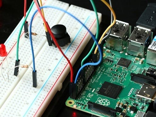
In this sample, we will connect a Push Button and LED to Raspberry Pi 2. We will be reading the status of the Push button and control an LED using GPIO.
This is a headed sample, so please ensure that your device is in headed mode by running this command: setbootoption.exe headed (changing the headed/headless state will require a reboot).
Also, be aware that the GPIO APIs are only available on Windows IoT Core, so this sample cannot run on your desktop.
Components
You will need the following components :
- a Raspberry Pi 2
- a EG1311-ND Tactile Button
- a red LED
- a 330 Ω resistor
Connect to your Device
Let’s start by wiring up the components on the breadboard as shown in the diagram below.
Here are the schematics:
Connecting the LED
Connect the cathode (the shorter leg) of the LED to Pin 31 (GPIO 6) of the Raspberry Pi 2
Connect the anode (the longer leg) of the LED to one lead of the 330 Ω resistor
Connect the other end of the 330 Ω resistor to Pin 1 (3.3V) on Raspberry Pi 2
Connecting the Tactile Button
Connect one pin of the push button to Pin 29 (GPIO 5) of the Raspberry Pi 2
Connect the other pin of the push button to the ground
Here is the pinout of the RPi2:
Building and running the sample
- Download the MS-IOT samples zip from here.
- Open
samples-develop\PushButton\CS\PushButton.csprojin Visual Studio. - Select
ARMfor the target architecture. - Go to
Build -> Build Solution - Select
Remote Machinefrom the debug target - Hit F5 to deploy and debug. Enter the IP address of your device and select
Nonefor the authentication type.
Let’s look at the code
First, we open the GpioPin resources we’ll be using. The button is connected to GPIO5 in active LOW configuration, meaning the signal will be HIGH when the button is not pressed and the signal will go LOW when the button is pressed. We’ll be using the LED, connected to GPIO6, which is connected in active LOW configuration, meaning driving the pin HIGH will turn off the LED and driving the pin LOW will turn on the LED.
buttonPin = gpio.OpenPin(BUTTON_PIN);
ledPin = gpio.OpenPin(LED_PIN);ode>
We initialize the LED in the OFF state by first latching a HIGH value onto the pin. When we change the drive mode to Output, it will immediately drive the latched output value onto the pin. The latched output value is undefined when we initially open a pin, so we should always set the pin to a known state before changing it to an output. Remember that we connected the other end of the LED to 3.3V, so we need to drive the pin to low to have current flow into the LED.
// Initialize LED to the OFF state by first writing a HIGH value
// We write HIGH because the LED is wired in a active low configuration
ledPin.Write(GpioPinValue.High);
ledPin.SetDriveMode(GpioPinDriveMode.Output);ode>
Next, we set up the button pin. For the Raspberry Pi 2, we take advantage of the fact that it has built-in pull up resistors that we can activate. We use the built-in pull up resistor so that we don’t need to supply a resistor externally.
// Check if input pull-up resistors are supported
if (buttonPin.IsDriveModeSupported(GpioPinDriveMode.InputPullUp))
 buttonPin.SetDriveMode(GpioPinDriveMode.InputPullUp)
else
 buttonPin.SetDriveMode(GpioPinDriveMode.Input);ode>
Next we connect the GPIO interrupt listener. This is an event that will get called each time the pin changes state. We also set the DebounceTimeout property to 50ms to filter out spurious events caused by electrical noise. Buttons are mechanical devices and can make and break contact many times on a single button press. We don’t want to be overwhelmed with events so we filter these out.
// Set a debounce timeout to filter out switch bounce noise from a button press
buttonPin.DebounceTimeout = TimeSpan.FromMilliseconds(50);
// Register for the ValueChanged event so our buttonPin_ValueChanged
// function is called when the button is pressed
buttonPin.ValueChanged += buttonPin_ValueChanged;ode>
In the button interrupt handler, we look at the edge of the GPIO signal to determine whether the button was pressed or released. If the button was pressed, we flip the state of the LED.
private void buttonPin_ValueChanged(GpioPin sender, GpioPinValueChangedEventArgs e)
{
 // toggle the state of the LED every time the button is pressed
 if (e.Edge == GpioPinEdge.FallingEdge)
 {
 ledPinValue = (ledPinValue == GpioPinValue.Low) ?
 GpioPinValue.High : GpioPinValue.Low;
 ledPin.Write(ledPinValue);
 }ode>
We also want to update the user interface with the current state of the pin, so we invoke an update operation on the UI thread. Capturing the result of an async method in a local variable is necessary to suppress a compiler warning when we don’t want to wait for an asynchronous operation to complete.
// need to invoke UI updates on the UI thread because this event
// handler gets invoked on a separate thread.
var task = Dispatcher.RunAsync(CoreDispatcherPriority.Normal, () => {
 if (e.Edge == GpioPinEdge.FallingEdge)
 {
 ledEllipse.Fill = (ledPinValue == GpioPinValue.Low) ?
 redBrush : grayBrush;
 GpioStatus.Text = "Button Pressed";
 }
 else
 {
 GpioStatus.Text = "Button Released";
 }
});
That’s it! Each time you press the button, you should see the LED change state.


Comments
Please log in or sign up to comment.