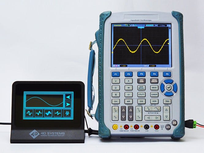
In this project, we will make a function generator using the gen4-uLCD-43DCT-CLB display module. The gen4 display will be used for generating various types of signal waveforms namely: square, triangular, sinusoidal, sawtooth, and noise waveform. The frequency of the periodic waveforms can also be adjusted.
How it Works
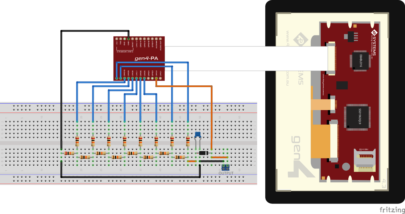
Step 1: Build- Build the circuit as shown in the diagram.
Step 2: Program- Open the Visi project using Workshop 4. This project uses the Visi Environment.
- You can modify the properties of each widgets and buttons.
- The upper limit for the increment steps for adjusting the frequency can also be adjusted in the section shown below. (Note: Larger increment steps will produce higher frequency, but the output waveform shape might not be preserved.)
- You can check and modify the code section for the square wave generator shown below. The equation in the conditional statement can be modified to adjust the duty cycle of the square wave output.
- You can check and modify the code section for the triangular wave generator shown below. The peak and bottom values can be adjusted within the range of 0 to 255
- You can check and modify the code section for the sinusoidal wave generator shown below. The generation for each point in the sinusoidal waveform is done in the sineVal() function, this function can be improved to generate more sample points for a smoother waveform.
- You can check and modify the code section for the sawtooth wave generator shown below. The peak values can be adjusted within the range of 0 to 255.
- You can check and modify the code section for the noise generator shown below. The peak value can be adjusted within the range of 0 to 255.
- You can check and modify the code section for the graphing function used for displaying the waveform in the display.
- You can also add additional waveform functions to the function generator
- You can also change the border colors, the scope trace color, and the buttons of the function generator.
Step 3: Compile- Click on the “Compile” button.
Note: This step could be skipped. However, compiling is essential for debugging purposes.
Step 4: Comms Port- Connect the display to the PC. Make sure that you are connected to the right port. Red Button indicates that the device is not connected, Blue Button indicates that the device is connected to the right port.
Step 5: Compile and Upload- Go back to “Home” tab. This time, click on the “Comp’nLoad” button.
- Workshop 4 will prompt you to select a drive to copy the image files to a uSD Card. After selecting the correct drive, click OK.
Step6: Mount uSD Card- When the uSD card is not yet inserted, this message will appear on your gen4 Display: "Drive not mounted"
- After inserting your uSD card this GUI should appear on the gen4 Display:
Demonstration


Comments
Please log in or sign up to comment.