
Hardware components | ||||||
 |
| × | 1 | |||
 |
| × | 5 | |||
 |
| × | 5 | |||
 |
| × | 1 | |||
| × | 1 | ||||
Software apps and online services | ||||||
 |
| |||||
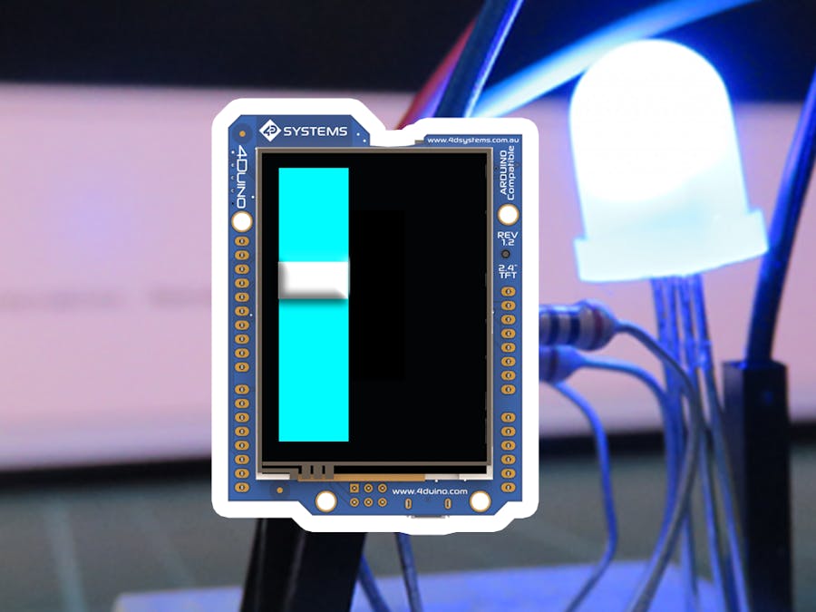
In this lesson, we’ll conduct a simple yet interesting project - create an LED ladder and manipulate it via I/O ports and touch display Slider.
The LED works on the basic principle that when potential difference is applied across the anode and cathode, light is emitted. LEDs have polarity, and will only work if current flows from the anode to the cathode, therefore positive must always be connected to the anode and ground to the cathode. The longer lead of the LED is the anode whilst the shorter lead is the cathode. A resistor is placed before the anode in order to lower the current flowing through the led. This will extend the lifespan of the LED and dim the brightness to a level that is more comfortable to look at.
Note: If you end up clipping the leads, the anode lead can be found by looking inside the LED and examining the metal contacts. The larger contact is the cathode, and the side of the cathode will be flat on the outside.
- LED x 5
- 220Ω Resistor x 5
- Jumper cables
- Micro USB cable
Build the circuit as shown in the following diagram and schematic.
Workshop 4 – 4Duino Basic Graphics environment is used to program this project. (The same could be implemented in the latest Arduino IDE).
This project requires the Arduino IDE to be installed as Workshop calls the Arduino IDE for compiling the Arduino sketches. The Arduino IDE, however, is not required to be opened or modified to program the 4Duino.
Open this file using Workshop 4.
Note: Download the project here.
Step 3: Comms PortConnect the 4Duino to the PC using uUSB cable.
Then navigate to the Comms tab and select the Comms port to which the 4Duino is connected.
Finally, go back to “Home” tab and now click on the “Comp’nLoad” button.
Now moving the slider on the 4Duino Display, you can control LED ladder.


Comments