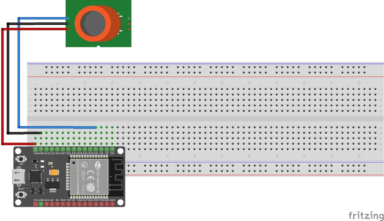
First, make the wiring
Read more- Prepare tools and materials such as project board, ESP-32, MQ-135 sensor, and jumper cable
Tools and Materials
- Install the ESP-32 and MQ-135 sensor components on the project board
- Connect the VCC pin of MQ-135 to pin 5V on ESP-32 with jumper cable
sc
- Connect the GND pin of MQ-135 to the GND pin on ESP-32 with jumper cable
- Connect pin A0 on MQ-135 to pin 35 on ESP-32 with jumper cable
- Take some widgets from the widget box in Blynk such as value display, chart, icon, level H, button, and LCD
- create 4 value displays to show the gas levels of CO2, CO, CH4, NA3
- create datastream for each gas level CO2 (V1), CO (V5), CH4 (V6), NA3 (V7). as in the picture
- Create Datastream (V9) for level H, as the threshold of C02 gas
- Create Datastream (V10) for icon, as an indicator of the CO2 hasa threshold
- Create Datastream (V0) for Button, as On/Off
- Open Arduino ide, open tools then select board (DOIT ESP32 DEVKIT V1)
- Create a program like the picture below, and fill in ssid with your Wifi name and Wifi password. then fill in auth with the token obtained from Blynk
- enter the code according to the GitHub link (https://github.com/Rvldilhm/Project-Monitoring-Air-Quality/tree/be3c1c42362aac6ba1a9bbcfeff71459a217dc5d)
- upload the program, then observe on the blink application. if it is connected then the gas level data CO, CO2, CH4, and NA3 will be sent to Blynk and displayed on the Blynk application.


Comments
Please log in or sign up to comment.