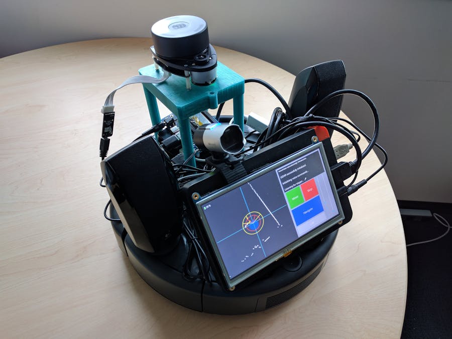
This project was created to eliminate confusion and tardiness while navigating to conference rooms. The completed project will guide the user to the conference room of their choice along the shortest path.
As an exercise, you can extend this project by implementing any of the following features:
- A basket to transport items.
- A user interface to display highlighted route on floorplan during navigation.
- An application to parse visual representations of floorplans for setup.
- A heuristic for path calculation in terms of room numbers, if room numbers correlate with their locations on the floorplan.
- An option for multiple floors and turn angle calculation (besides right/left).
- An option for user to configure robot to have a set HOME location.
- Set up your Joule according to these instructions. Technically, any Windows IoT Core compatible device should work with this project, since the IoT device communicates with the LIDAR and Roomba through the serial interface over USB.
- Remove the top plastic piece from your Roomba so the serial port is accessible.
- Use a 3D printer to print out the stands for the display/battery and LIDAR, as well as the Joule case.
- Attach the parts, then mount the display, battery, Joule, and LIDAR to the Roobma. Securely fasten a microphone and speaker to it (bonus points if you make your own mount for them!).
- Plug in the Joule to the battery and the display + LIDAR to the Joule via the provided cables.
In order for the Voice Recognition to work correctly, the robot needs to be connected to the internet. You can connect to WiFi through the Windows Device Portal.
https://docs.microsoft.com/en-us/windows/iot-core/connect-your-device/setupwifi
Setting up UART- You will need the hardware ID for the Roomba's and LIDAR's USB-to-UART cables. You can get them running the UART Sample app to detect and print all available serial devices https://github.com/ms-iot/samples/tree/develop/SerialUART/CS .
- Once you get the device IDs, you should set the values to the Roomba and Lidar device ID variables in the code. This is done so that there's no port mix-ups when having several serial devices connected. (These IDs are tied to the cables themselves, not the Roomba or the Lidar. In case you have more than one, each cable will have a different ID.)
You will need to give your robot a name so it can listen for it before trying to understand instructions, similar to the way you have to say "Hey Cortana" before telling Cortana any commands. You can specify the name of your robot in the VoiceCommandController.cs file.
Creating the mapMap information of rooms and intersections for a floor is stored in an XML file. This map information should include relative coordinates of each of these "waypoints" (a room or an intersection) along with distances in meters between connecting waypoints.
Setting up the starting point of the robotBecause the robot does not have a GPS, we need to specify a known starting location for the robot. You can set this using the SetStartingPosition() method in the Navigation code.
Setting up telemetryThe Roomba will report certain events like collisions to Azure IoT hub. In order to use this functionality, you will need an Azure IoT Hub subscription. After you get this subscription, you can replace the strings in the Telemetry.cs file so that the robot will connect to your Hub.
How to use the UIThe App has a single page that displays diagnostic information about the robot and provides a few buttons to manually make the robot move, stop, navigate, and turn off.
- On the left side of the app, there is an area that will plot all the points that the LIDAR returns, allowing the user to see what the robot is seeing. The blue circle represents the Roomba. The yellow circle and wedge represent the area the LIDAR looks at when making decisions on whether to adjust the Roomba's current trajectory or not. The red circle and wedge represent the area the LIDAR looks at when deciding whether to stop or not. Dots that enter these "cones" change color to indicate that they are in decision-making range.
- Towards the top there is an indicator of how much battery is remaining in the Roomba (aka iRobot Create 2).
- In the upper right corner, there is an output text block that prints out messages relating to what the robot is doing and can serve as a tool for debugging.
- The Move button moves the robot forward and then stops. This button is primarily to demonstrate how to make the Roomba move. It is also used for debugging obstacle avoidance algorithms.
- The Stop button stops the Roomba's currently-executing movement.
- The Navigate button starts the navigation for the Roomba from the source location to the destination. This is only a sample, so you'll have to replace the map XML file in the project to get it to navigate in your environment.
- The Off button sets the Roomba to OFF mode. When the Roomba is initialized it is set to FULL mode. Please refer to the iRobot Create 2 Open Interface Specification for more information on how the Roomba is operated. This is useful to get the Roomba out of FULL mode for charging, since it will not charge in FULL mode.
- The two sliders adjust the radius and the field of view of the yellow circle to the left.
- First set the robot name in the VoiceCommandController.cs file.
- Once you set the name, you can say one of the activation phrases (e.g. "Hey DJ Roomba") to activate the voice commands.
- Once the activation phrase is recognized, you can say a command (e.g. "Go to Room 2071").
- Example code for how to handle voice commands can be found in the ControllerPage.xaml.cs file.
- Try to avoid tilted and irregular floors, the current design will have a hard time given that it's basing off its position from the encoders alone.
- Due to how the Roomba reports encoder readings, the current implementation is not able to handle reverse movement.
- When choosing a name for the robot, we recommend using a strong-sounding and unambiguous name with at least 3 syllables.
- When starting the app, the Roomba should start at your defined starting point and face in the positive y-direction as determined by the coordinates you provide in your map XML.


Comments
Please log in or sign up to comment.