


Hardware components | ||||||
 |
| × | 1 | |||
Software apps and online services | ||||||
| ||||||
This guide is Sponsored by M5Stack who sponsor most of my projects (thank you for the opportunity to work with you) and Labist who sponsored the ET4 3D Printer I use : https://labists.com/collections/3d-printing/products/3d-printer-et4-diy-kit.
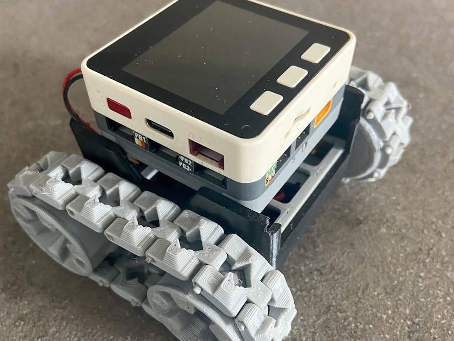
Is this project I will show you how to control a SMARS Tracked Chassie using an M5Stack fitted with a GoPlus module.
The Electronics.The Particular M5Core I'm using is from the M5Go pack sponsored by M5Stack https://m5stack.com/
Fitted with the M5GoPlus Module: https://shop.m5stack.com/products/goplus-module?_pos=2&_sid=e4ef4b596&_ss=r&variant=17116939583578
However you can use the newer Core2 And Goplus two as they use the same footprint.
You can Buy the Core2 from This Link and the Goplus2 module from This Link.
In order to fit the GoPlus or GoPlus2 the M5Stack Core or M5Stack Core2 you need to remove the 4 screws that hold the base to the core. The Core2 on the other hand will need the expansion board removed first.
The Core on the left is missing two screws because I didn't have two long enough. the expansion board of the Core2 is the white section with CORE2 printed on it. When removing the Core2's base plate be careful. The Core2's batter is stick to the base but unlike with the core, the batter is connected to the core main PCB.
On the original cores, the batterie is only connected in the base however with the Core2 models the battery (as mentioned is connected to the main PCB and held to the base with tape and clips. You need to gently flex the Core2's base plate to release the battery and then place it on top of the main pcbs components (don't worry about sticking down as once fastened back together, the battery will be held in place.
The Goplus2's battery is stuck to the silver plate, gently peel the battery away from the plate and carefully fit to the base as shown.
DO NOT DAMAGE THE SILVER WRAPPER OF THE BATTERIES OR THEY WILL CATCH ON FIRE!Now all you need to do is align the big connectors and carefully assemble the M5Stack Cores with the GoPlus modules and bases.
You will also need to purchase a pair of N20 motors.
I won't post a link to these because I don't have an affiliate link and they can be purchased from all over the web for a variety of varying prices.
The SMARS Chassie.SMARS stands for Screwed/Screwless Modular Assembleable Robotic System and is an Open Source project created by Kevin Thomas and is downloadable from SMARS on Thingiverse.
A big shout out goes to Kevin McAleer who must be Kevins biggest fan and set up the SMARSFan learning site found here: https://www.smarsfan.com
Follow this link to the thingiverse page, download and print the latest version of SMARS.
The Stock SMARS Chassie just firs the M5Stack dimensions with a little bit of flexing.
Connecting the Motors.
The N20 motors need two cables soldered to them, fortunately theses cables come with the GoPlus modules and have connectors needed to fit them to the modules motor connectors.
Solder the cables to the motors and place them in the chassis so that the cable poke out like in the image.
Next tuck the excess wire into the base, plug the cables into the GoPlus and flea the chassis slightly to allow the M5Stack to fit in.
Programming M5.A.R.S.
In order to program the M5.A.R.S. we will be using M5Stack online IDE UIFlow.
In order to drive the two N20 motors that moves the tracks we need to use the motor block found under the GoPlus or GoPlus2 menu.
For both the GoPlus and GoPlus2 the motor speed is a range of -127 up +127, a strange value range and it has taken me a long time to find this range hidden in documents.
The following example should move the M5.A.R.S forward for a second and then backward for a second.
if the M5.A.R.S rotates instead of moving back and forth it means one of the motors is wired wrong.
Do not worry as it does't matter because we can just swap the 127 to -127 or vice verser in order to correct the movement.
Now we have the M5.A.R.S moving we can start to do some more interesting things. As the motors don't have encoders built in we have to estimate travel distance using the following formula : D=SxT (Distance equals Speed X Time). Unfortunately this isn't very accurate as the Time is controlled by a "Wait" block which is also effected but the time it take a loop to be run and Speed is the values of -127 to +127 which is effected but friction in the printed parts, motors and surface traveled on.
We can try to measure the distance and for that I used a free downloadable paper ruler from here: http://www.vendian.org/mncharity/dir3/paper_rulers/UnstableURL/ruler_foot_a4.pdf
Glue this to a piece of board, place the M5.A.R.S onto the end so that the front edge is directly inline with the 0cm (or 0 inch for imperial users. And yes in the UK we still use imperial when dealing with sheet materials :P )
Now run the following several times to see where the M5.A.R.S stops and this will give us a base idea of travel distance.
In this image and in my case we can see that in two seconds it traveled a distance of 27.1cm. What I am not showing is that in my case I have some drift and the M5.A.R.S actually travelled towards the bottom of the ruler by about 5mm. Repeat 5 times to get the point that its stops, find the average of the values and you can use the value to set the wait timing to better control the forwards and backwards movement.
Turning is worked out in almost the same way except that instead of using a ruler we use a printed protractor downloaded from here : https://www.cool2bkids.com/wp-content/uploads/2019/08/Printable-Protractor.pdf
Place the M5.A.R.S on the centre of the printed protractor
Run the following code:
And check where it ends.
Repeat this step to find the average and then we can use mathematic to calculate how long we need to move to make it move 90 degrees.
Once we have our measurements, we can now (somewhat) accurately tell how far the M5.A.R.S moves when we send it command.
If you found this useful please like, follow and let me know.
If you have any questions, please feel free to ask.


Comments
Please log in or sign up to comment.