When two hearts meet they start beating. Both the hearts need to be ON and within a range to blink. If you turn off either of the heart or go out of range they will stop blinking.
I divided this project in three sections:
- Electronics
- Assembly
- Software
Let's get started!
Electronics:- nRF24L01+
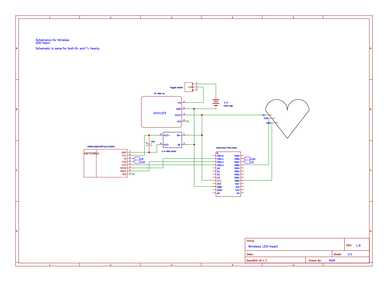
The nRF24L01+ chip is the key component of this project. It uses 2.4Ghz band for communication and also has features like AutoACK, sleep mode, and IRQs. Also, it has an onboard antenna which saves the space.
I used SMD version of the chip instead of the Main module because it's small and less bulky and in fact, I got a better range of ~40-50m with it.
The only drawback of SMD version is the soldering pads are small so either you need to use breakout board or solder wires directly onto the board.
- Neopixel LEDs
This time I went with Neopixels because one, you get RGB in a small form-factor and second, it has microcontroller inbuilt so you won't need an external driver circuit which saves the space. I made a custom PCB for this project.
- Power Supply
I used 1000 mAh Lipo to power everything. The Pololu step up converter boosts 3.7v from Lipo to 5v for Arduino and Neopixel PCB. The nRF chip uses 3.3v for its operation which is powered by the buck converter which takes 5v from booster and provides a 3.3v. The booster can boost voltage to 5v from ~1v so you get the most of the juice from the battery.
The current consumption of entire circuit when running is about 800 mAh. And when powered down it goes to around ~20 mAh which is still a lot and that's because even when the Neopixels are turned off they have the quiescent current draw of 1mA so that's 12 mAh + other components like boost/buck converters. You can also add a MOSFET to switch Neopixels on/off.
The nRF has a sleep mode which when put into, it only consumes 900nA but then it depends on software implementation. Because if you're using IRQs to check data availability you can't put a chip in sleep and the standby current is ~15mAh. We'll get into the optimization/ power saving part in the software section.
AssemblyFor this project, I used a Christmas/party decoration plastic heart box. It is compact to fit in the palm but also has enough space to fit all circuitry inside it. The box I used was 80x75x50mm in dimensions.
- I used foam-core board cut in a heart shape template to hold components. The board is easy to cut through and also has the strength to hold the substantial amount of weight without bending.
On the bottom side of foam-core, I glued Lipo onto which I glued nRF chip. The buck converter was glued near the Lipo which made 3.3v system separate from the 5v rail.
On the top side, Arduino and 5v booster was glued close to each other, onto which I glued neopixel PCB directly. I crammed everything into base part of the box in order to keep the free space between PCB & lid as much as possible to allow light to spread uniformly.
I divided the container's base into two sections: the nRF chip + Lipo battery + buck converter in the bottom and on the top I put Arduino + boost converter + Neopixel PCB.
This kept the nRF chip separated from other components from blocking its antenna affecting its range.
To diffuse light more I sprayed them with White spray paint. This is how they look before. As you can see with transparent lid the light doesn't diffuse at all.
For the nRF chip I used latest RF24 library and for the Neopixels I used FastLED.
To communicate between two hearts, I made one heart Tx and other Rx. The good thing about nRF is that, it has autoACK so you don't need to change the modes from Tx<-->Rx continuously, the chip does that for you automatically. The autoACK can be used for bi-directional communication. Also, it provides IRQs to interrupt MCU to check data.
There are multiple ways of doing communication between modules. You can poll every N seconds to check if data is available or use IRQs to wake up MCU from sleep.
In polling, you can put nRF to sleep for N seconds and let MCU wake it up. But when using IRQ you need to keep the nRF chip on standby which consumes ~15 mAh continuously.
The third way is to put both MCU and nRF in sleep and let Watchdog Timer interrupt MCU from sleep. This way is most efficient in terms of power consumption, but it takes more time to establish a connection as you need both the modules up and running. The pseudocode for the Watchdog timer would be:
Tx side:
1) Transmit for N seconds
	2) if we recieve ACK
			then blink LEDs for N seconds
	3) put MCU and NRF in sleep
	4) Watchdog timer would wake up MCU after N seconds
	5) goto 1
Rx side:
1) Either poll every N seconds or use IRQs to get data
	2) if we receive packet:
		send ACK back
		Blink LEDs for N seconds
	4) If not using IRQs
		put both MCU and NRF to sleep
		Watchdog timer would wake up MCU after N seconds
        5) If using IRQs
                set Interrupt
                put MCU to sleep
                read data
You can find the Polling and Watchdog interrupt examples in the code section.
And this is it. Thanks for reading and Happy Valentine's Day!


_3u05Tpwasz.png?auto=compress%2Cformat&w=40&h=40&fit=fillmax&bg=fff&dpr=2)
Comments