


Hardware components | ||||||
 |
| × | 1 | |||
 |
| × | 1 | |||
 |
| × | 1 | |||
 |
| × | 1 | |||
| × | 4 | ||||
| × | 1 | ||||
Years ago I built a driving simulator enclosure which has a compartment for a PC. This compartment has two doors, each with two PC fans in them to circulate air in the compartment. Initially I had the PC fans in these doors plugged into the motherboard of the PC because it was a dedicated PC for the simulator. However, nowadays I need to easily remove the PC to use it at my desk. Constantly plugging and unplugging these fans from the motherboard is not practical so I decided to build this stand-alone PC fan controller.
Here is the PC compartment opened up without the PC in it...
The 4 wires hanging are to connect the 4 fans. In the upper left you can see the white DHT22 sensor on its small red PCB. The fan and sensor cables go into the dashboard of the simulator (inside the enclosure) where I have a panel with the push-button and LED as well as other push-buttons to control ceiling and footwell lighting, PC compartment LED lighting and power to a car radio in the dashboard. The two grey boxes on the left have 220 VAC and 12 VDC relays that I have things connected to and that I am controlling from the dashboard with an Arduino MEGA.
Connecting the PC takes a couple of minutes by simply placing it in this compartment and plugging in the power, USB, audio and HDMI cables already in place on the left.
This is the compartment closed off with its front cover pushed into place...
The PC is a standard full-tower PC with a glass door panel which exactly fills the center hole. The fans in the right door (on the front side of the PC) are intake fans blowing air into the compartment, and the fans on the left (on the back side of the PC) are exhaust fans extracting air out of the compartment.
I am missing a dust filter on the left door. If anyone has a Corsair Obsidian 7500 Airflow Edition PC enclosure and they would like to sell or donate their front airflow dust filter please let me know in the comments section :-)
FunctionalityAll 4 fans (two intake and two exhaust fans) are controlled with a push-button with an indicator LED. Pushing the push-button for less than 2 seconds and then releasing it turns the fans on (and the LED) in the default temperature controlled mode at a minimum speed / duty cycle (20% PWM duty cycle as recommended by the manufacturer of the fans I am using).
In this mode the speed of the fans will be automatically adjusted every 10 seconds based on the current temperature relative to the temperature when the Raspberry Pi Pico first came on. The speed of the fans progressively increases as the temperature rises to reach a maximum speed when the temperature reaches 5 or more degree above the temperature when the Pico started. The fans will remain in minimum duty cycle should the temperature decrease below the initial temperature when the Pico started (so they will never automatically turn off).
The temperature sensor is installed in the PC compartment. I chose to use the temperature when the Pico first starts as a reference point because when I want to use the simulator I turn on a master power switch which turns on the power to everything, including this fan controller. At this point the PC has not been turned on yet, therefore the PC compartment is at room temperature. If I use the PC for a while and later turn on these fans, the fans will turn faster if the temperature has risen significantly since everything was turned on, hopefully cooling things back down quickly and closer to the initial room temperature.
A second short press (< 2 seconds) of the push-button will turn the fans off (and the LED).
When the fans are on (in any of the 4 modes available) and the push-button is pressed and held down for more than 2 seconds, the fans will switch to the next fan mode which is a fixed 50% duty cycle (when we are in the initial/default temperature controlled mode) and the LED will blink slowly. If the push-button is released within the next 2 seconds then this mode will stay active (50% duty cycle, no temperature control).
If, on the other hand, the push-button remains pressed down, after another 2 seconds it will switch to the next mode which in this case will be the fixed 75% duty cycle with the LED blinking faster. Keeping it pressed down for another 2 seconds will switch to the next mode which is the fixed 100% duty cycle (maximum speed) with the LED blinking really fast. Keeping it still pressed down for another 2 seconds will cycle back to the temperature controlled mode, and so forth. Put another way, if you hold down the push-button it will keep switching to the next mode every two seconds until you release it allowing you to easily choose a mode using this single on/off push-button.
Additional FeaturesThe following are other notable features:
- Fan Checks / Testing
When in the temperature controlled mode only, the controller takes a temperature reading every 10 seconds, adjusts the fan speeds / PWM duty cycle and then checks each fan to see if they are turning. If a fan is not turning (because it is stuck, burned out or not plugged in) it will set it to 0% PWM duty cycle (off) and it will blink the LED 3 quick pulses every 10 seconds to indicate that there is one or more faulty fan. When a fan is faulty it will not be checked again unless all fans are turned off and back on (which will re-start the default temperature controlled mode). If none of the fans are working either from the get-go or because progressively each fan became faulty while in the temperature controlled mode, the controller will automatically set itself in the off state (all fans off), cut the 12 volt power to all fans and turn off the LED. - Fan Modes
As mentioned in the previous section, there are 4 fan modes:
1) Temperature Controlled mode
2) 50% PWM fixed duty cycle mode
3) 75% PWM fixed duty cycle mode
4) 100% PWM fixed duty cycle mode
The fixed duty cycle modes will not adjust the fan speed depending on the temperature nor do they check if the fans are rotating. The reason for this design choice is that I expect to mostly keep the controller in the default temperature controlled mode and rarely use the fixed PWM modes, but I wanted this flexibility of being able to force the fans at certain fixed speeds should I want to.
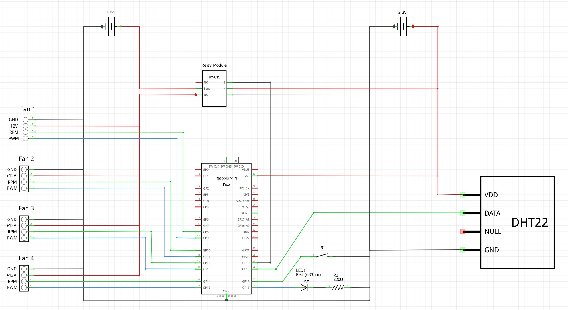
- Be sure to connect the ground of the 12 VDC power supply (powering the fans) to the ground of the Pico as shown in the schematic. If you don't do this then the ground levels could be different and the LOW states of the PWM signal generated by the Pico are likely to not be interpreted as LOW states by the fans, and likewise the LOW states of the fan RPM pins are likely to not be interpreted as LOW states by the Pico.
- As power supply I use an off-the-shelf 12 VDC power supply to power the fans and a 12 to 3.3 volt buck converter to power the Pico, temperature sensor and relay module. In all of my projects I usually don't use the 3.3 volt output of the Pico to power anything so that I don't have to worry about whether or not the components connected are pulling too much current from the Pico's limited capability.
- I chose to use a Raspberry Pi Pico because PWM can be set on every digital pin as well as hardware interrupts, whereas most Arduinos only have a few dedicated pins for this functionality.
- I deliberately attach one hardware interrupt at a time on the fan to be checked, and then detach it after the 100 millisecond check / calculation of RPM, so that these hardware interrupts don't interfere with the timing of communications with the temperature sensor. This is good practice anytime communicating with external digital devices where timing is critical which a triggering hardware interrupt would interfere with / corrupt the timing.
- I could have permanently connected the PC fans to their 12 volt power source but chose to use a relay as the fans I am using have LEDs and I didn't want to keep these lit while the fans are not running.
- An even better implementation would be to use a relay per fan to be able to independently fully turn each fan off (as opposed to one relay to turn them all off or on at once). However, PC fans are quite reliable and since mine are well protected from anything getting into them, I chose to use one relay but still thought it would be useful to check if they are running and indicate when there is a problem (I have forgotten to plug one in or something).
- While doing some research prior to deciding to build this, I read that in general it is best to use a 5 volt logic board with PC fans that use PWM, both for generating the PWM signal but also to monitor the RPM pin of the fan to count fan revolutions. Using the 3.3 volt logic level Pico has posed no issues with the fans I am using though. I suspect most fans will work with a 3.3 volts PWM signal because this is a sufficiently high voltage for the fan to consider it as a HIGH state. Also, from my oscilloscope observations, the RPM pin is in a tri-state mode (meaning it is not brought LOW or HIGH) when the fan is not turning. When the fan starts turning, it is pulsed LOW twice per revolution and then floats again during the rest of the time between pulses. Therefore, voltage also does not matter with this sensor pin. In fact, this pin needs to be connected to a pull-up resistor to bring it HIGH when it is in the "floating" state (INPUT_PULLUP pin mode in the sketch) otherwise it is not possible to reliably count pulses / revolutions.
- Not all PC fans are alike, so whenever you buy one make sure to check what DC volts it requires (typically 5 or 12 VDC), if it is a 4 pin PWM controlled fan (vs. 3 pin without PWM), what its minimum PWM duty cycle is, how much current it needs, its maximum RPM speed and noise level, air displacement, etc.!
- I could have checked the fan rotation speed / RPM of each fan vs. the PWM duty cycle to monitor for significant speed variations between fans at a given duty cycle but chose not to because tests with the fans I am using showed that there is no discernable difference between them.
- The sketch can be easily updated to cater for fewer or more fans and is thoroughly documented (many comments throughout the code).
- I commented out the code to activate the Serial port as well as the various Serial.print commands. If you want to more easily understand how it all works while having the Pico connected to your computer, I would recommend uncommenting this code.
The temperature controlled mode works very well in my implementation. I tested it for several hours playing a demanding simulation on the PC while monitoring the temperature and fan RPMs being reported (connecting the Pico to my computer and uncommenting all of the Serial.print statements in the code). The temperature slowly increased to just below 2 degrees Celsius above the initial room temperature with the fans progressively increasing speed to approximately 900 RPM at which point the temperature stabilized. At this speed the fans I am using are still pretty quiet so it didn't bother me for them to stay running at this speed while playing. Once I stopped playing the temperature decreased over time with the fans slowing down in-step.
The fan speeds/duty cycles could be more aggressively increased for every degree increase which should lower the temperature at which the fans are circulating enough air to keep the temperature from rising further. How well this works will obviously depend on every implementation - how much heat your PC generates, how effectively your fans are evacuating the air, etc.
I hope you found something useful in this project. Thanks for taking an interest in it, good luck with your projects and... ENJOY THE JOURNEY!!!

Comments
Please log in or sign up to comment.