DescriptionThe goal of this project is that it is very simple to reproduce - using left-over electronics and parts you have in your home. The largest show-stopper is probably that the housing needs to be 3D-printed, and possibly that it's designed for a 10W LED (which is of course not as popular as the normal effect LEDs we all have lying around). However! At least when it comes to the electronics, the project is highly flexible! Most, if not all, parts can be swapped out and replaced with what you find convenient in your own workshop.
The idea is that you could replicate this project using anything from 1 hour (+ printing time of around 6 hours for a 2mm layer 0.4mm nozzle print) to a couple of days, depending on how "polished" you want the looks to be. The electronics can be made in 30 minutes if you have all parts available, the assembly will take minimum 30 minutes, but will take a lot longer if you want to paint and make it look as nice as possible.
Details3D Files (STL and customizable STEP files): https://www.thingiverse.com/thing:3943356
In the video above you can follow our build process and a detailed explanation of the circuitry and the design choices that were made.
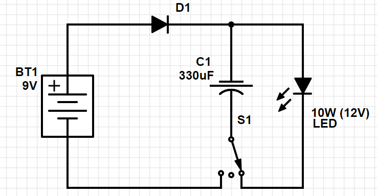
The simplest possible circuit is really simple. Using a 3-state switch (shown in the video), where the middle state is "do nothing" and the two other states represents charging and discharging of the capacitor - this is what the schematic looks like:
There is no current limiting resistor to protect the LED because it's specified to run at 12 Volts, and the battery will only provide 9 Volts. In the design we used ourselves we actually did place a small 3 ohm resistor in series with the LED, but as shown above, that is not strictly necessary. So if you want to make the soldering-job as easy as possible. Go with the design above.
Alternative Circuit DesignsIn our design we also included a discharge resistor that will make sure that the capacitor doesn't stay charged over long periods of time by evening out the potential stored over the capacitor. The value of this resistor obviously needs to be quite high, so it doesn't allow the voltage to even out immediately, but unfortunately I didn't write down the exact value we used, so the 10k in the following schematic is just a guess.
The next alternative circuit is the one that we actually used on the bread board in the video at the top. Here you can see that the 3 ohm current limiting resistor is included, as well as a two button system that replaces the tri-state switch. This allows for a constant current path through the LED, bypassing the charging and discharging of the capacitor - by holding down both buttons at once. This gives the possibility to use the Neuralizer as a flashlight.
The switches can also be replaced with simple two-state toggle-switches, but then the R_bleed resistor must be removed because the equivalent to one of the swithes S1 and S2 in the circuit above will always be "pushed" (eg. the toggle switch will always connect one of the two ways). That would mean that R_Bleed will leave a constant current path between the anode and cathode of the battery - draining it.
Next up comes a variant that uses a "normal" LED rated at 2V and ish 20mA. Here, the current limiting resistor must be taken into account, otherwise, the circuit stays the same.
There are more ways to do this circuit, depending on what parts you have available. It is also possible to mix and match between the alternatives posted above.
Finish with spray paintThe selection of spray paint we used to finish the build. From the left: Plastic filler, black primer, silver paint, clear coat.
To get rid of those pesky layer lines from the 3D print, we spent a whole while sanding down the surface. Then we did several rounds of filling cracks with the plastic filler (just a generic car bumper filler from our local hardware store) and repeating the sanding between each time.
1 / 11 • Slideshow of important steps along our process of finishing the printed parts with a metallic look
After assembling all the electronics, we sprayed another layer of filler, in a hope to get rid of the seams between each 3D-printed part, sanded this down slightly with fine grit sand paper, then started painting. We first used a black primer, then a silver paint and finished with a clear coat to give it an extra reflective look, and also to protect the paint. Between each layer we waited approximately 10 minutes, while it was hanging outside in a slight breeze. The layers were probably not completely dry within this time, so we wouldn't have wanted to touch it, but they were dry enough for the paint to look nice. When all the layers were sprayed on, we brought the thing inside (just holding the supporting thread we used to hang it up with) and let it hang inside for 24 hours before touching it.We were quite happy with the end result. The seams weren't completely gone, as the pictures above will show you, but they were pretty close to gone! Had we used a putty based filler in addition to the spray paint filler we used, we could probably have removed the seams entirely. The layer lines were nowhere to be seen.


Comments
Please log in or sign up to comment.