Sparkfun wishlist imports have been deprecated
Giovanni Carrera
Published

A LCD Serial Terminal with Teensy

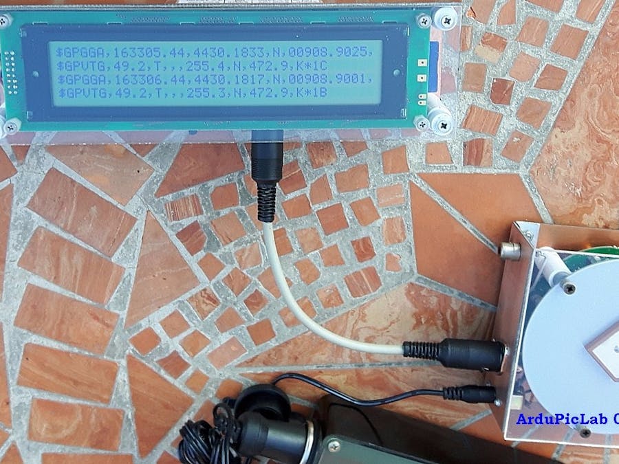
This project uses a serial 40x4 LCD display with a Teensy board to help a compact serial terminal receiver to be connected to many systems.

IntermediateShowcase (no instructions)10 hours2,434
A LCD Serial Terminal with Teensy

Things used in this project

Hardware components

Teensy 3.1
Teensy 3.1
×1
LCD 40x4 display
×1

Story

Read more

Schematics

lcd40_J8RK1nkY8i.gif

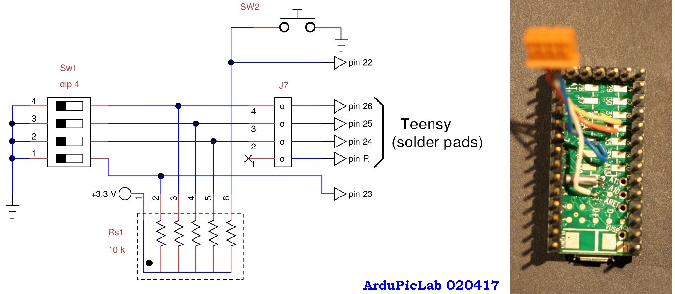
With minor changes to the wiring diagram and the program you can connect the dip switches to the pins available on Teensy connectors and avoid soldering the wires on the pad. For example, renouncing the SD interface, you can use the pins 9, 10, 11 and 12.

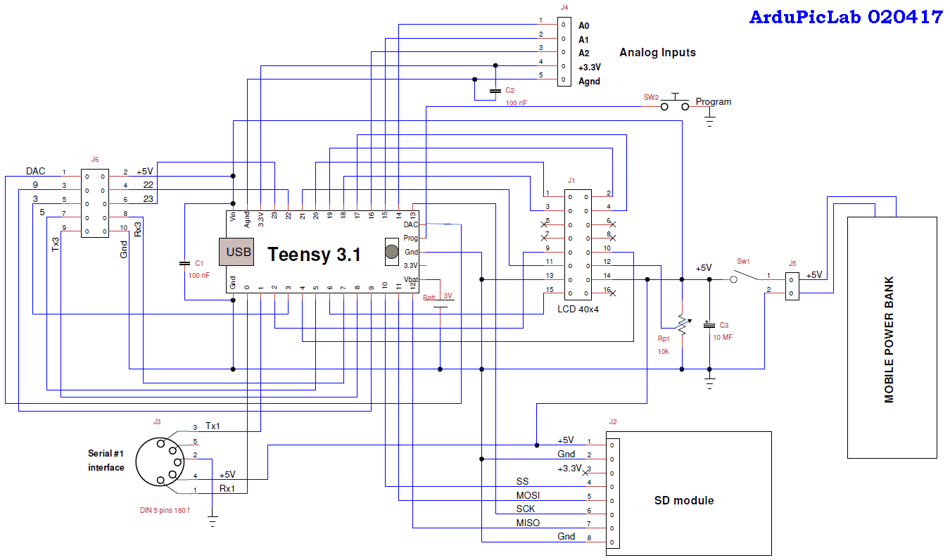
lcd40_VdFQR0jD0C.gif

This scheme includes some components that are not used in this project as J2, J4 and J6 connectors, SD interface and the Lithium battery for Teensy RTC. Because all pins on the Teensy connectors are previously engaged, I used for the dip switches some signals from solder pads on the back side of the board. As can be seen in the following figure, I wired four signals (pins 24, 25, 26 and R) to a small connector J7, located on the back of the Teensy board. The following figure shows the wiring diagram of dip switch and pull-up resistors, mounted on the breadboard. The SW2 button is not used in this project.

Code

Untitled file

Arduino
To realize a real serial terminal it would be better to have an automatic scrolling of received lines, so a buffer is necessary. I used a string array of 4x41 characters. A string size of 41 is necessary to represent a line of a maximum of 40 characters because strings have a null character (ASCII code 0) as a terminator.
For the first four lines received, the printing proceeds from line 0 to line 3. Subsequently, each new line is printed on line 3 while the other three previous lines are shifted up. This operation is done in the buffer: before transferring the last line received in the buffer#3, the current content of the buffer#3 is put in buffer#2 and so on until the contents of the buffer#1 is transferred to the buffer# 0. The whole behaves like a multidimensional shift register. After this process all the buffers are printed at one time on LCD.
/*Serial terminal, print on a 40x4 LCD display,
  the library LiquidCrystalFast is used because it controls
  also display with double enable pins as that used
  Giovanni Carrera - 07/03/2017
*/
// include the library code:
#include <LiquidCrystalFast.h>
// set this to the hardware serial port used
#define HWSERIAL Serial1

const int Button = 22; // push button
const int DipSw1 = 23; // dip switch bit 1
const int DipSw2 = 24; // dip switch bit 2
const int DipSw3 = 25; // dip switch bit 3
const int DipSw4 = 26; // dip switch bit 4
const long baud_rate[9] = {1200, 2400, 4800, 9600, 19200, 38400, 57600, 115200};
String linestr;
char displayline[4][41];// display buffers 4 rows x 40 characters
int r, i;
boolean ft_flag = true;// first time flag

// initialize the library with the numbers of the interface pins
//LiquidCrystalFast lcd(RS, RW, E1, E2, D4, D5, D6, D7);
LiquidCrystalFast lcd(21, 4, 2, 6, 17, 18, 19, 20);

void setup() {
  pinMode(DipSw1, INPUT); // set dip switch bits to input
  pinMode(DipSw2, INPUT);
  pinMode(DipSw3, INPUT);
  pinMode(DipSw4, INPUT);
  pinMode(Button, INPUT);
  // set up the LCD's number of rows and columns:
  lcd.begin(40, 4);
  // Print a message to the LCD.
  lcd.println("Serial terminal by GCar - 07/03/2017");
  // read dip switches for baud rate coding
  int brcode = digitalRead(DipSw1) + digitalRead(DipSw2) * 2 + digitalRead(DipSw3) * 4;
  lcd.print("Baud rate = ");
  lcd.println(baud_rate[brcode]);
  HWSERIAL.begin(baud_rate[brcode]);// for Teensy
  delay(5000);
  for (r = 0; r <= 3; r++) {
    displayline[r][0] = 0; // clear buffer
  }
  LCDprint(); // clear display
}

void LCDprint() {
  lcd.clear(); // clear diplay
  for (r = 0; r <= 3; r++) {
    lcd.setCursor(0, r); // set the cursor to column 0, line r
    lcd.print(displayline[r]); // print all four lines
  }
}

void loop() {
  r = 0;
  if (HWSERIAL.available() > 0) {
    linestr = HWSERIAL.readStringUntil('\n');
    if (ft_flag == true) {
      linestr.toCharArray(displayline[r], 41);// store line in buffer
      LCDprint();// print all four lines
      r++;
      if (r > 3) {
        r = 0;
        ft_flag = false;
      }
    }
    else {
      for (i = 0; i <= 40; i++) {
        displayline[0][i] = displayline[1][i];// scroll, line#0 = line#1
        displayline[1][i] = displayline[2][i];// scroll, line#1 = line#2
        displayline[2][i] = displayline[3][i];// scroll, line#2 = line#3
      }
      linestr.toCharArray(displayline[3], 41);// store new line in line#3
      LCDprint();// print all four lines
    }
  }
}

Credits

Giovanni Carrera
14 projects • 50 followers
Electronic Engineer
Contact

Comments

Please log in or sign up to comment.