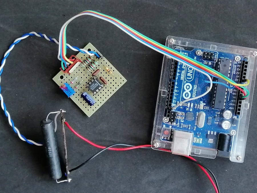
There are several breakout boards available on the market ready to measure the current with Arduino, but for those who love self-construction I suggest to carry out this project. It is a fairly accurate current sensor while using common components.
The most accurate system for current measurement is to use a shunt, i.e. a resistor with very low resistance compared to that of the load and the generator. The voltage drop on this resistor, according to Ohm's law, is proportional to the current that passes through it.
Of course today we also find on the market sensors based on the Hall effect, that are devices that measure the magnetic field generated by the current passing through a wire for the well-known Ampere’s law, but these semiconductor sensors do not have comparable stability and precision.
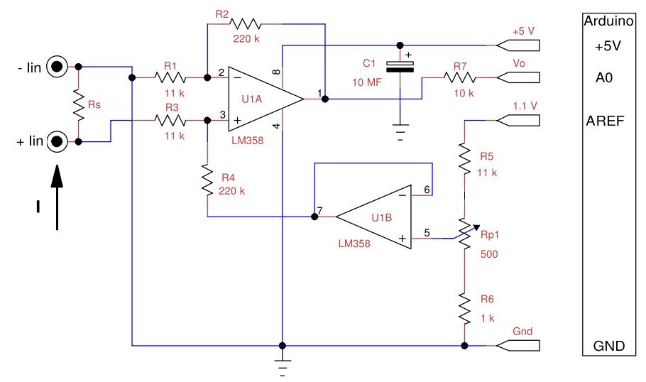
To measure the voltage drop I used the shunt connected in a low-side way, i.e. towards ground and a differential amplifier.
The operational amplifiers, due to the saturation of the output stage, fail to give a zero at the output in the case of single power supply. I solved this problem by adding a constant Vsh = 100mV which I then delete via software. The output of differential amplifier U1a is:
Vo = (Vi+ - Vi-)×R2/R1+Vsh
The second operational U1b, connected as voltage follower, generates the voltage Vsh by means of a divider on the Arduino Aref.
For correct operation the following relations must be respected: R1=R3 and R2=R4 with very low tolerances. The ADC converter has a full scale of 1100mV and I take 100 out of it to make the zero, so I can have 1000 mV for the measurement, this means that the maximum input voltage must be 1000/20 = 50 mV. To have a sensitivity of 75 mV, suitable for many commercial shunts, it is sufficient to set R1 = R3 = 15kΩ and R2 = R4 = 200kΩ, standard and easily available values.
To test this circuit I used a 0.1 Ω shunt resistor and a 0.1 A current source.
A more detailed description of this project can be found in my blog: http://ardupiclab.blogspot.it/.
The following figure shows the layout and the connections of the components of my prototype, made on a small pre-drilled PCB board.


_ztBMuBhMHo.jpg?auto=compress%2Cformat&w=48&h=48&fit=fill&bg=ffffff)


Comments
Please log in or sign up to comment.