


Hardware components | ||||||
| × | 1 | ||||
| × | 1 | ||||
 |
| × | 1 | |||
| × | 1 | ||||
| × | 3 | ||||
| × | 1 | ||||
 |
| × | 1 | |||
| × | 1 | ||||
 |
| × | 1 | |||
Software apps and online services | ||||||
 |
| |||||
Hand tools and fabrication machines | ||||||
 |
| |||||
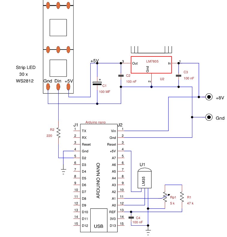
The idea came to me by experimenting with the intelligent RGB LED strips that is equipped with a control microchip, like the NeoPixel based on a WS2812B chip. The interesting thing is that just one bit is enough to control numerous chip LEDs. The number of pixels is not limited by the signal level, always retransmitted by each chip, but by the transmission speed. Each LED consumes up to 20 mA, so 60 mA maximum per chip. If I wanted to represent a light bar with 30 LEDs of white light, that is with the three colors on, I would have a consumption of 1.8 A with considerable dissipation and variation of current. In order to drastically reduce the current I prefer to turn on only one LED at a time using one of primary colors RGB and also reducing its brightness.
The following figure shows the appearance of the LED strip I used.
The sensor I used is an LM35, it is an analog sensor with output proportional to degrees Celsius with a slope of 10 mV/°C. Its measurement range is from 2 to 150 °C and, with particular circuits, it can measure up to -55°C. To measure the room temperature it is an economic sensor that also requires a simple software.
More details on this project are on my blog: http://ardupiclab.blogspot.it/
The scale of my display has 30 RGB LEDs starting from 5 °C up to 34 °C. For this range the sensor output ranges from about 50 to 340 millivolts. If the Arduino ADC converter has Vref=5V (default), the resolution is about 5mV, or 0.5°C. But the supply voltage is not stable and varies significantly depending on whether Arduino is powered via USB or from external input Vin. If I program analogReference (INTERNAL) the resolution becomes almost 1 mV because the internal reference of the ADC is about 1.1 V (from 1 to 1.2 V) and is also much more stable than the default mode. Because of these reasons I used this reference even if the display resolution is one degree.
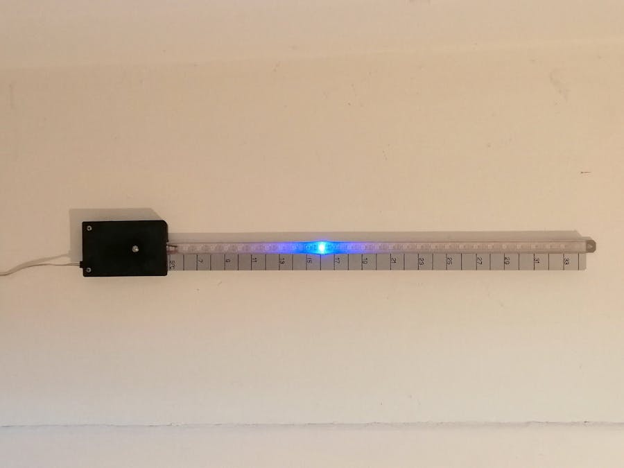
Prototype constructionThe simplest constructive solution is to buy the LED strip aluminum profile complete with its diffuser and to transfer on it the thermometric scale numbers.
I used a "U" aluminum profile of about 15x10 mm, 600 mm long for a total of 30 LED chips with a scale from 5 °C to 34°C. The strip has a density of 60 LEDs per meter, so the pitch is about 16.7mm.
At the end of the bar I fixed a small box containing the electronics, while beside the LED bar I glued an "L" shaped profile of about 10x20 mm on which I drew the thermometric scale with a normographe, then I painted it with a transparent varnish for protection. This solution, quite "do it yourself" is visible in the cover image. The writing can also be done with a label printer or with self-adhesive numbers.
The average consumption of myprototype is around 50 mA, this also because I only turn on one LED at a time and also reduced its brightness. The power supply is similar to that used for Arduino, preferably use voltages between 7.5 and 9 volts, even not stabilized.
I used an Arduino Nano because it is compact and with a 0.1" pitch, necessary for prototyping matrix board. The sensor is connected to pin A0 and I have connected a potentiometer on pin A1 to calibrate the thermometer without modifying the program. For the prototype I used a matrix board, as shown in the following figure. Notice at the top the sensor thatcomes out of the box.
The program
For this program I used the Adafruit_NeoPixel library (https://github.com/adafruit/Adafruit_NeoPixel) for the LED strip, because it is simpler and more compact.
Nothing prevents you from using more leds to enlarge the scale, updating the program on the #define NUM_LEDS 30 line and also modifying the control of the leds. With some modifications we can use a scale in Fahrenheit and with hardware and software interventions we can extend the scale even to negative values.
The display resolution is one degree, so I convert the temperature that is of float type to integer and address with this the LED to turn on.
The LED chip[0] is the one at the bottom: it islit blue for a temperature of 5 °C or flashes violet for lower temperatures. The LED chip[29] is the highest one and lights up red for a temperature of 34°C or flashes yellow for higher temperatures.
My program turns on the LED chips based on thefollowing criteria:
- Chip led[0] a violet flash of 1 second for T < 5°;
- Chip led[0÷17] blue LED on for 5°≤ T <18°;
- Chip led[18÷14] green LED on for 18° ≤ T≤ 24°;
- Chip led[25÷29] red LED on for 25° ≤ T≤34°;
- Chip led[29] yellow flash of 1 second for T >34°C.
Of course it is very easy to change the limits to better adapt them to personal wellbeing thresholds.
The function pixels.Color() sets the colors with three bytes corresponding to the primary colors, respectively: R (Red) G (Green) B (Blue). The intensity of the colors varies from 0, 0, 0 corresponding to the LEDs that are all off (black) up to 255, 255, 255 for the three LEDs that are on (white). Varying the intensity of the individual LEDs the displayed color varies.
As already seen, the program reads the potentiometer to make a correction of about -3° up to + 6°.
At the beginning I put VREF = 1050 mV, thisvalue is obtained by measuring the voltage with a digital voltmeter, otherwiseput VREF = 1100.


Comments
Please log in or sign up to comment.