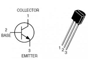
When you want to drive a load that needs high values of current and/or voltage and and a digital control is needed (Arduino in this case), is not possible to use mechanical switch. For this reason electronic device that work as digital switches (ON/OFF) are used (BJT and MOS).
2. Electronic buttonsAs for mechanical buttons the current flow can be stopped opening the positive pole or the negative one. This methods are called high-side driving or low-side respectively. This tutorial will show how to design a circuit for low-side driving.
First of all you need to choose a transistor. In this tutorial we will use the famous 2N2222, but all the rules used can be used for any NPN BJT. We will design something like this.
With this configuration when a digitalWrite(pin, LOW) instructions is used the switch is open stopping the current flow in the load, while a digitalWrite(pin, HIGH) instruction is used the switch is closed flowing current in the load.
Since the load (the thing that you want to turn on/off, e.g. relay, power LED) is known we can already choose the power supply value and the current the load needs to work. So we have to design only the base resistor RB.
6. Voltage & Current limitsThe power supply value and the current that flow in the load are used to choose the transistor. In fact, with these parameters, we to check the VCEO and the Collector Current of the chosen transistor. From 2N2222 datasheet:
So we have to choose a load with a power supply value <40V and a current <600mA. In this example we are going to consider a load that needs a power supply of 12V and a current of 150mA.
8. DC current gainFrom the datasheet the DC current gain (hFE) in this conditions is 100:
The hfe is necessary in order to calculate the Ib and the RB as a consequence.
IB=3IL/hfe=3*150mA/100 =4.5mA
To design the RB we have to find in the datasheet the maximum VBEsat of the chosen transistor with our parameters (Vcc and IL).
10. Design the resistor base RBIn this case VBEsat = 1.2V
Now we can design the RB:
RB = (5V -1.2V)/4.5mA =844Ω
Choosing a commercial value:
RB =820Ω
P.S: In this example the used Arduino as a 5V logic. If we want to use a 3.3V logic (Arduino DUE):
RB = (3.3V -1.2V)/4.5mA =466Ω
Choosing a near commercial value:
RB =470Ω


_ztBMuBhMHo.jpg?auto=compress%2Cformat&w=48&h=48&fit=fill&bg=ffffff)


Comments
Please log in or sign up to comment.