

Hardware components | ||||||
_ztBMuBhMHo.jpg?auto=compress%2Cformat&w=48&h=48&fit=fill&bg=ffffff) |
| × | 1 | |||
| × | 1 | ||||
| × | 1 | ||||
| × | 1 | ||||
 |
| × | 1 | |||
 |
| × | 1 | |||
 |
| × | 1 | |||
Software apps and online services | ||||||
 |
| |||||
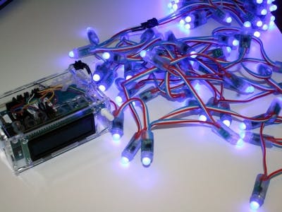
The Arduino GSM shield makes it possible to control your Arduino board in several ways. This lesson should help you to learn and understand how you can use simple SMS messaging to control the output of the board. The project was originally done for an interactive light post, which was displayed on the annual meeting of Innovation Center of Iceland in February 2014. In addition to the products on the inventory list, a WS2801 digital RGB LED pixel string and a 5V power source are used. The WS2801 LED string has a controller chip connected to each RGB LED pixel, making it possible to control brightness and color of each pixel individually.
The sketch can easily be manipulated to control relays, motors or other outputs of your choice.
The LCD screen is not necessary for the project, but if you set this up where you can’t use a serial monitor, it can be nice to see the status of the GSM connection and the received messages on the screen.
2. The circuitConnect the LED pixel string to the GSM shield, data cable to pin 6 and ground to, well, ground. To wire your LCD screen to your Arduino, connect the following pins:
- LCD RS pin to digital pin 12
- LCD Enable pin to digital pin 11
- LCD D4 pin to digital pin 5
- LCD D5 pin to digital pin 4
- LCD D6 pin to digital pin 3
- LCD D7 pin to digital pin 2
Additionally, wire a 10K pot to +5V and GND, with it's wiper (output) to LCD screen's VO pin (pin3).
Connect the external power source to the LED string. If you are using several LED strings, connect data and ground in a serial connection, but it is best to connect each LED string parallel to the power source.
It is actually possible to power up both the Arduino with GSM shield and one LED strip with one 9V battery.
The sketch is divided into four chapters (plus the introduction). First chapter is for calling the libraries, defining constants and global variables. Second chapter is the setup of communications, third is the loop itself, and the fourth chapter is for definition of functions.
The code for the LCD screen is mostly nested together so it should be easy to comment it out or remove it if you don’t use it. It is though not necessary.
4. Definition of global variables, constants and calling librariesThere are three libraries included in the sketch. One for the GSM shield, one for the LCD screen and in for the Pixel strip. The first two are a part of the Arduino IDE, but the last one you need to download and install in your system. Available here
If you are comfortable with working on libraries, you can open up the libraries and manipulate them to make them smaller. The GSM library for example is large, but in this project you only use the SMS functions so you can actually exclude voice call or data network. Just remember to save it as a new library with another name, so the whole GSM.h library will be accessible in the future.
Next there are few constants defined. First the PINNUMBER constant, that is used when the GSM shield activates the SIM card. Second is for declaring the output pin for the LED pixels. The last constants are for declaring the output pins for the LCD screen.
Next is the setup of functions for the LED pixels. This is done by calling an Adafruit_NeoPixel class from the Adafruit NeoPixel library, here named LED.
Adafruit_NeoPixel LED = Adafruit_NeoPixel(150, PIN, NEO_GRB + NEO_KHZ400);
This class takes on four variables that you change here if your setup is different. For example if you have fewer lights or different type of LED pixels.
First variable is the number of lights, here 150. Second is the pin output, here assigned with the constant PIN previously defined and given the value 6.
Next variable sets how the pixels are wired;
- NEO_GRB is for GRB bitstream (Green, Red, Blue) most neopixels
- NEO_RGB is for RGB bitstream (Red, Green, Blue)
Finally it addresses the frequency of the bitstream
- NEO_KHZ800 for 800 KHz bitstream
- NEO_KHZ400 for 400 KHz bitstream
For interacting with the GSM shield, we call two classes from the GSM library. First we call the GSM class function, here given the name gsmAccess, and then the GSM_SMS class function, here given the name SMS.
Last part of chapter 1 is declaration of global variables, that can be accessed anywhere in the sketch.
#include <Adafruit_NeoPixel.h> // This includes Pixel library from ADAFRUIT. Awailable here https://github.com/adafruit/Adafruit_NeoPixel
#include <GSM.h> // This includes the GSM library, included in your Arduino IDE
#include <LiquidCrystal.h> // This includes the LCD library, included in your Arduino IDE
#define PINNUMBER "" // declaration of the constant PINNUMBER used to push the pin number of the SIM card
#define PIN 6 // declaration of the constant PIN, and setting it to output nr. 6
LiquidCrystal lcd(12, 11, 9, 8, 5, 4); // sets the pinnumbers used for the LCD display. Comment out if no LCD
Adafruit_NeoPixel LED = Adafruit_NeoPixel(150, PIN, NEO_GRB + NEO_KHZ400);
/* This sets values to the variables in the NeoPixel class function.
First variable is the number of lights,
then it is the output, previously defined as nr.6
Next variable sets how the pixels are wired
  NEO_GRB is for GRB bitstream (Green, Red, Blue) most neopixels
  NEO_RGB is for RGB bitstream (Red, Green, Blue)
Finally it addresses the frequency of the bitstream
  NEO_KHZ800 for 800 KHz bitstream
  NEO_KHZ400 for 400 KHz bitstream
*/
GSM gsmAccess; // opens up GSM access on the shield.
GSM_SMS sms;
char remoteNumber[20]; // Variable to store the remote number from the modem.
char c; //Variable for reading the sms messages from the SIM card
char m; //Variable for storing the first letter in each messages
int x=0; //Counter for the number of SMS messages processed
char lastm; //Variable to stop SMS replying
String lastMess; //for storing the whole message
int countR, countG, countB, countY, countW, countP, countO; //Counters for keeping information on how often each class is called
The setup chapter is mostly for setting up the GSM shield. In addition there are two methods of monitoring set here and the setup for the lights. First the serial monitor and second the LCD screen. It can be nice to have the serial monitor working while you are testing connections and manipulating the sketch. If you want to test the hardware or update the software later it is also nice to have the serial monitor working. The LCD screen is, as previously stated, not necessary. But if your Arduino and GSM shield are not connected to a computer, it can be good to see the status of the system. It is even possible to add a push button to be able to get further information from the software on the screen, such as number of messages received.
The setup of the GSM is straight forward. First you define a Boolean variable notConnected and set it to true. This variable indicates if the GSM shield has network connection or not. (no connection if true, connection if false). Next there is a while loop that tries to connect through gsmAccess if notConnected returns true. gsmAccess.begin has one parameter, the pin number of the SIM card. Write the pin number in quotes, like this: gmsAccess.begin(PINNUMBER”1234”) if the SIM card has a pin number.
void setup() {
  //Setup for SMS recieving. Serial setup makes it possible to monitor the status on your PC while connected
  Serial.begin(9600);
  Serial.println("SMS Recieving");

  // LCD setup is for the LCD screen. Comment it out if you dont set it up.
  lcd.begin(16, 2);
  lcd.print("SMS recieve");

  boolean notConnected = true; // this defines a variable that indicates no GSM connection if true
  while(notConnected) {  // if there is no connection, the program runs gsmAcess. gsmAcess returns GSM_READY when connected
    if(gsmAccess.begin(PINNUMBER)==GSM_READY) // If you have a PIN number on your SIM card, write it as parameters here in quotes. PINNUMBER"9876"
    notConnected = false;
    else {
      //messages printed on the serial monitor or LCD screen, then it tries again in 1000 milliseconds
      Serial.println("No connection");
  //Code for the LCD screen, comment out or remove if note used.
      lcd.setCursor(0, 1);
      lcd.print("No connection");

      delay(1000);
    }
  }
  // if connection is established
  Serial.println("GSM connected"); //GSM connected
  Serial.println("Waiting"); //Waiting for SMS

  //Code for the LCD screen, comment out or remove if note used.
  lcd.clear();
  lcd.print("GSM connected");
  lcd.setCursor(0,1);
  lcd.print("Waiting");

  //Setup for the lights

  LED.begin();
  LED.show();
}
There are two main functions in the loop.
First is the reading of messages. It starts with a sms.peek function that returns the first byte of incoming messages. We assign it to the variable m, to use with the switch-case function later. Next there is a while loop, where we assign the value of the SMS messages to the variable c and build a String variable that keeps the value of the entire messages. The sms.read function returns the messages one byte each time so if you want to use the whole messages later, for example for reporting, forwarding or replying, it is wise to store it in a variable.
Now it is time for the switch-case statement. The switch statement checks the value of variable m, or the value of the first letter in the message in this case. If this char matches any of the cases, the sketch runs the code in the case block. Just remember to end each case with the break keyword to avoid running all the code below unintentionally. The cases that control the color of the LED call a function called oneByOne that takes two variables, first the variable LED.color(xxx,xxx,xxx), a specific variable for setting the color to the Pixels. Second variable is a delay time in milliseconds, and indicates the waiting time before next pixel is turned on. A counter for keeping track of how many times each case is increased here and the status sent to the serial monitor, and finally a delay for 5 seconds pauses the program so it will not seek another SMS immediately.
I only show three cases here, but you can find it all at the end of the lesson.
The case Q is a little different as it does not call the function. Instead it replies with a SMS message to the last remote number, indicating how often the system has received since it was started.
void loop() {
  lastMess = "";
  //reading messages
  if (sms.available()) // if there are SMS on the SIM card
  {
    x++; //message counter adds one
    sms.remoteNumber(remoteNumber, 20);

    //Show the message on monitor
    Serial.println("Messages received from");
    Serial.println(remoteNumber); //Prints senders number on the serial monitor
    Serial.println("Message:");
  //Code for the LCD screen, comment out or remove if note used.
    //Show the message on LCD
    lcd.clear();
    lcd.setCursor(0,0);
    lcd.print(remoteNumber);
    lcd.setCursor(0,1);
    lcd.print("Message: ");
    lcd.setCursor(11,1);

    m = sms.peek(); //sms.peek looks up the first byte in the messages.
    //By storing it in the global char variable m, it is possible to use it later for the swich-case function

    while(c=sms.read()) {
      String nextChar = String (c);
      String Mess = (lastMess + nextChar);
      lastMess = Mess;
      /*sms.read collects one digit of the messages at time and stores it in the variable c.
      This while loop builds a String variable "lastMess" from each byte in the messages for displaying.
      */
    }

    Serial.println(lastMess); // prints the whole messages on the monitor and LCD screen
    lcd.print(lastMess);

    switch (m){ //Checks the value of the variable m where the sketch has stored the first letter of the SMS. Runs the case according to the value.

      case 'R':    //sets the lights to red with the function eittiEinu
        oneByOne(LED.Color(0, 255, 0), 50); // the parameters of the function are two, the strip color, and the delay time in milliseconds for each pixel
        countR = countR++;
        Serial.print(countR);
        delay(5000); // Sets a delay time in milliseconds. The loop will not search for a new SMS untill this time is out
        break;

      case 'Z':    // turn off the lights
        oneByOne(LED.Color(0, 0, 0), 50);
        delay(5000);
        break;

      case 'Q':     // If you send the letter Q as SMS, you will recieve an SMS in return indicating the number of SMSÃ
In this sketch is only one function declared. This function does two things:
- First, it sends a reply message to the sender, thanking for his choice but this is only done if the value of m is unequal to the value of lastm. This is done to prevent the program to send SMS messages each time it runs the loop.
- Second it turns on the pixels, one by one in the color assigned in the case and with the delay time defined in the case.
void oneByOne(uint32_t l, uint8_t bid) {
  if (m != lastm)
  {
        sms.beginSMS(remoteNumber);
        String Reply ="Thank you for your message : " + lastMess;
        sms.print(Reply);
        sms.endSMS();
  }
  for(uint16_t i=0; i<LED.numPixels(); i++) {
      LED.setPixelColor(i, l);
      LED.show();
      delay(bid);
  }//end for

    sms.flush(); //discards the SMS message
    lastm=m;
}
I like to keep things in order, so I designed a box for the system made of 3 mm thick clear acrylic plastic, cut with an Epilog laser. The drawings are in PDF format here but don't hesitate to contact me for other formats.
Here is the complete code:
/*
***** SHINE ON YOU (Crazy Diamond) ***** https://www.youtube.com/watch?v=R0sw2CgysWY
GSM interface of LED/GSM lightpost.
Designed and written for the annual meeting of Innovation Center of Iceland in February 2014.
This sketch makes it possible to control the color of digital RGB LED light pixels with SMS messages. It can easily be manipulated to control
relays, motors or other outputs of your choice. The idea behind this project is to make outdoor lightning interactive. This can be useful for example to
light up your driveway as you drive home from work or even to remotely light up your house to repell burglars when you are on holiday. This can also be used
for setting up charging posts for electric cars, where the user signs up with his GSM phone to activate the charging and gets the bill asigned to his GSM account.
Created by; Thorsteinn Tomas Broddason, Fab Lab Saudarkrokur
***** The circuit *****
For this project you need;
*Arduino Uno
*Arduino GSM shield
*LCD 16x2 display,
*WS2801 LED pixels connected to PIN 6
*Potentio meter
*5V Power source for the LED string
*12V Power source for the UNO and GSM shield
Connect the LED pixels to ground on the Arduino board and the data cable of the pixels to pin 6. Wire the LCD screen to the board as explained here:
LCD RS pin to digital pin 12
LCD Enable pin to digital pin 11
LCD D4 pin to digital pin 9
LCD D5 pin to digital pin 8
LCD D6 pin to digital pin 5
LCD D7 pin to digital pin 4
Wire a 10K pot to +5V and GND, with it's output to LCD screen's VO pin (pin3).
Schematics for the circuit awailable at www.fablab.is.
*/
// **** 1  Libraries, definitions and global variables ****
#include <Adafruit_NeoPixel.h> // This includes Pixel library from ADAFRUIT. Awailable here https://github.com/adafruit/Adafruit_NeoPixel
#include <GSM.h> // This includes the GSM library, included in your Arduino IDE
#include <LiquidCrystal.h> // This includes the LCD library, included in your Arduino IDE
#define PINNUMBER "" // declaration of the constant PINNUMBER used to push the pin number of the SIM card
#define PIN 6 // declaration of the constant PIN, and setting it to output nr. 6
LiquidCrystal lcd(12, 11, 9, 8, 5, 4); // sets the pinnumbers used for the LCD display. Comment out if no LCD
Adafruit_NeoPixel LED = Adafruit_NeoPixel(150, PIN, NEO_GRB + NEO_KHZ400);
/* This sets values to the variables in the NeoPixel class function.
First variable is the number of lights,
then it is the output, previously defined as nr.6
Next variable sets how the pixels are wired
  NEO_GRB is for GRB bitstream (Green, Red, Blue) most neopixels
  NEO_RGB is for RGB bitstream (Red, Green, Blue)
Finally it addresses the frequency of the bitstream
  NEO_KHZ800 for 800 KHz bitstream
  NEO_KHZ400 for 400 KHz bitstream
*/
GSM gsmAccess; // opens up GSM access on the shield.
GSM_SMS sms;
char remoteNumber[20]; // Variable to store the remote number from the modem.
char c; //Variable for reading the sms messages from the SIM card
char m; //Variable for storing the first letter in each messages
int x=0; //Counter for the number of SMS messages processed
char lastm; //Variable to stop SMS replying
String lastMess; //for storing the whole message
int countR, countG, countB, countY, countW, countP, countO; //Counters for keeping information on how often each class is called
// **** 2 Setup ****
void setup() {
  //Setup for SMS recieving. Serial setup makes it possible to monitor the status on your PC while connected
  Serial.begin(9600);
  Serial.println("SMS Recieving");

  // LCD setup is for the LCD screen. Comment it out if you dont set it up.
  lcd.begin(16, 2);
  lcd.print("SMS recieve");

  boolean notConnected = true; // this defines a variable that indicates no GSM connection if true
  while(notConnected) {  // if there is no connection, the program runs gsmAcess. gsmAcess returns GSM_READY when connected
    if(gsmAccess.begin(PINNUMBER)==GSM_READY) // If you have a PIN number on your SIM card, write it as parameters here in quotes. PINNUMBER"9876"
    notConnected = false;
    else {
      //messages printed on the serial monitor or LCD screen, then it tries again in 1000 milliseconds
      Serial.println("No connection");
  //Code for the LCD screen, comment out or remove if note used.
      lcd.setCursor(0, 1);
      lcd.print("No connection");

      delay(1000);
    }
  }
  // if connection is established
  Serial.println("GSM connected"); //GSM connected
  Serial.println("Waiting"); //Waiting for SMS

  //Code for the LCD screen, comment out or remove if note used.
  lcd.clear();
  lcd.print("GSM connected");
  lcd.setCursor(0,1);
  lcd.print("Waiting");

  //Setup for the lights

  LED.begin();
  LED.show();
}
// **** 3 The loop ****
void loop() {
  lastMess = "";
  //reading messages
  if (sms.available()) // if there are SMS on the SIM card
  {
    x++; //message counter adds one
    sms.remoteNumber(remoteNumber, 20);

    //Show the message on monitor
    Serial.println("Messages received from");
    Serial.println(remoteNumber); //Prints senders number on the serial monitor
    Serial.println("Message:");
  //Code for the LCD screen, comment out or remove if note used.
    //Show the message on LCD
    lcd.clear();
    lcd.setCursor(0,0);
    lcd.print(remoteNumber);
    lcd.setCursor(0,1);
    lcd.print("Message: ");
    lcd.setCursor(11,1);

    m = sms.peek(); //sms.peek looks up the first byte in the messages.
    //By storing it in the global char variable m, it is possible to use it later for the swich-case function

    while(c=sms.read()) {
      String nextChar = String (c);
      String Mess = (lastMess + nextChar);
      lastMess = Mess;
      /*sms.read collects one digit of the messages at time and stores it in the variable c.
      This while loop builds a String variable "lastMess" from each byte in the messages for displaying.
      */
    }

    Serial.println(lastMess); // prints the whole messages on the monitor and LCD screen
    lcd.print(lastMess);

    switch (m){ //Checks the value of the variable m where the sketch has stored the first letter of the SMS. Runs the case according to the value.

      case 'R':    //sets the lights to red with the function eittiEinu
        oneByOne(LED.Color(0, 255, 0), 50); // the parameters of the function are two, the strip color, and the delay time in milliseconds for each pixel
        countR = countR++;
        Serial.print(countR);
        delay(5000); // Sets a delay time in milliseconds. The loop will not search for a new SMS untill this time is out
        break;

      case 'Y':    //"Yellow"
        oneByOne(LED.Color(255, 255, 0), 50);
        countY = countY++;
        Serial.print(countY);
        delay(5000);
        break;

      case 'G':     //"Green"
        oneByOne(LED.Color(255, 0, 0), 50);
        countG = countG++;
        Serial.print(countG);
        delay(5000);
        break;

      case 'B':    //"Blue"
        oneByOne(LED.Color(0, 0, 255), 50);
        countB = countB++;
        Serial.print(countB);
        delay(5000);
        break;

      case 'W':    // "White"
        oneByOne(LED.Color(255, 255, 255), 50);
        countW = countW++;
        Serial.print(countW);
        delay(5000);
        break;
      case 'P':     // "Pink"
        oneByOne(LED.Color(20, 255, 147), 50);
        countP = countP++;
        Serial.print(countP);
        delay(5000);
        break;
      case 'O':    //"Orange"
        oneByOne(LED.Color(80, 255, 0), 50);
        countO = countO++;
        Serial.print(countO);
        delay(5000);
        break;

      case 'Z':    // turn off the lights
        oneByOne(LED.Color(0, 0, 0), 50);
        delay(5000);
        break;

      case 'Q':     // If you send the letter Q as SMS, you will recieve an SMS in return indicating the number of SMSÃ
SteiniBrodda
 Arduino_Scuola
Comments
Please log in or sign up to comment.