


Hardware components | ||||||
| × | 1 | ||||
 |
| × | 1 | |||
| × | 1 | ||||
| × | 1 | ||||
| × | 1 | ||||
| × | 1 | ||||
| × | 2 | ||||
| × | 20 | ||||
 |
| × | 1 | |||
| × | 1 | ||||
 |
| × | 1 | |||
| × | 2 | ||||
| × | 1 | ||||
| × | 1 | ||||
 |
| × | 1 | |||
 |
| × | 2 | |||
| × | 2 | ||||
| × | 2 | ||||
Winning project in the category of social innovation "Arduino Day Community Challenge 2019"
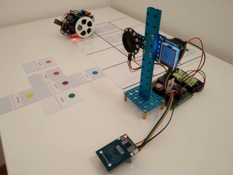
The final goal of this project is that children with visual impairment or blindness can use the Escornabot robot and therefore use educational robotics as a learning tool.
Escornabot is a Galician project of code / open hardware whose objective is to bring robotics and programming to children.
The operation is as follows:
On a board with squares for Escornabot we will have:
- A card that identifies the start of the route.
- A card that identifies the end of the route.
- Several cards marking the route between the starting point and the end point.
Each card will have its meaning printed in Braille in such a way that the child can "read" the route that the instructor or teacher has marked on the board.
Once the route is memorized, the child will have 6 cards:
- Card for the move forward.
- Card for the move back.
- Card for the movement to turn left.
- Card for the movement to turn to the right.
- Card for the action to reset the movements.
- Card for the action of executing the movements.
These cards, which represent the different instructions that can be sent to the robot, will also have their meaning in Braille.
When the child brings a card to the RFID card reader that is connected to the control board, several things will happen:
- A speech will be heard saying the movement or action associated with the card.
- The ring of 12 LEDs will illuminate with the color associated with the movement or action (in some actions there will even be a small animation with the LEDs).
- The TFT will show the drawing or text associated with the instruction.
- The instruction to the robot will be sent by bluetooth.
When the robot starts executing each of the movements, the following will happen:
- The robot will send by bluetooth to the control board each movement that it will execute.
- You will hear the speech of the movement or action that you are executing.
- The ring of 12 LEDs will illuminate with the color associated with the movement or action that you are executing.
- The TFT will show the drawing or text associated with the movement or action you are executing.
- When the Escornabot finishes each movement it will check and therefore read that there is an RFID card under it. If the robot finds a card, it means that it is on the right track. If, on the other hand, the robot does not find any card, it will mean that it has made a mistake and will send a message by Bluetooth indicating that it has been "lost" by inviting the child to try again. In this scenario the robot will stop and will not execute more movements.
- When the robot has finished finishing all the movements it will be validated if it has really reached the end. If it has reached the end, the robot will send a Bluetooth message as I have done it correctly and a message to the contrary in case it has not reached the expected end.
- If during the execution of the instructions a new movement or action is sent to the robot it will stop and all the previous instructions that it had will be reset (it is the same behavior that happens when we press any button of the Escornabot while it is executing movements).
As you can see there is a bidirectional communication between the robot and the board and at all times the child can see and / or hear both the instructions sent and all the movements that the robot is executing as well as the possible errors found during this execution.
The different steps we will have to take are:
- Installation of the necessary elements in the Escornabot.
- Creation of the control board and vertical structure with the visual elements (ring of LEDs and TFT) and the speaker.
- Connection of all the elements.
- Acquisition of the identifiers of the RFID MIFARE cards that we will use.
- Labeling of movement / action cards and cards present on the board.
- Creation of the audios in MP3 format that will later be recorded on a MicroSD card that we will insert into the MP3 player.
- Pairing of the control board with the Escornabot through the HC-05 and HC-06 modules.
- Loading the programs on the control board and the Escornabot
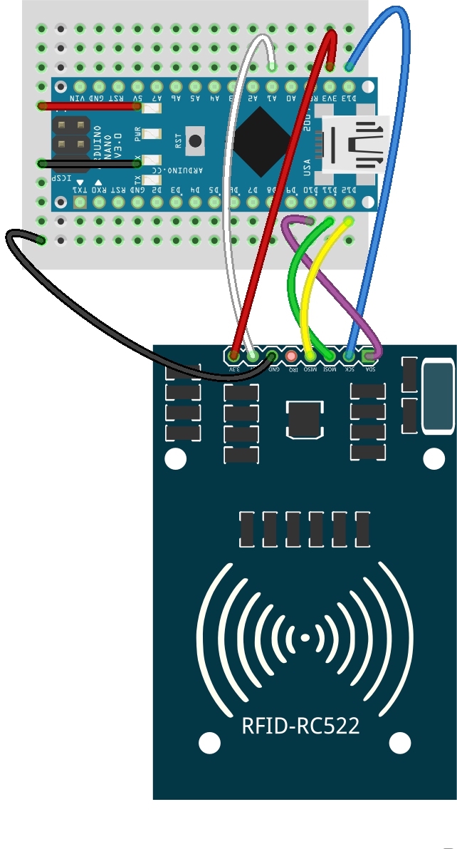
We will start by fixing the RFID-RC522 module to the bottom of the robot. This module will allow to read RFID MIFARE cards and will serve to check that the robot is traveling the correct way.
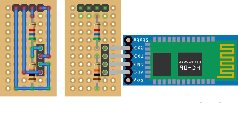
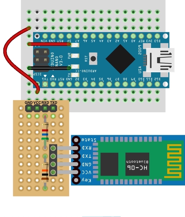
We will create a board to connect the bluetooth module HC-06 to the robot.
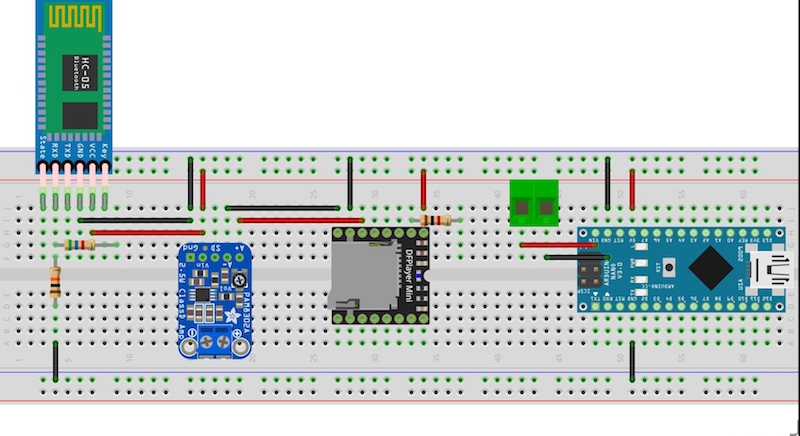
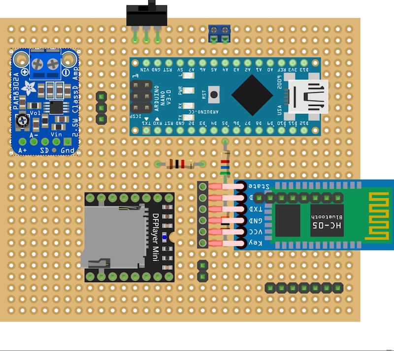
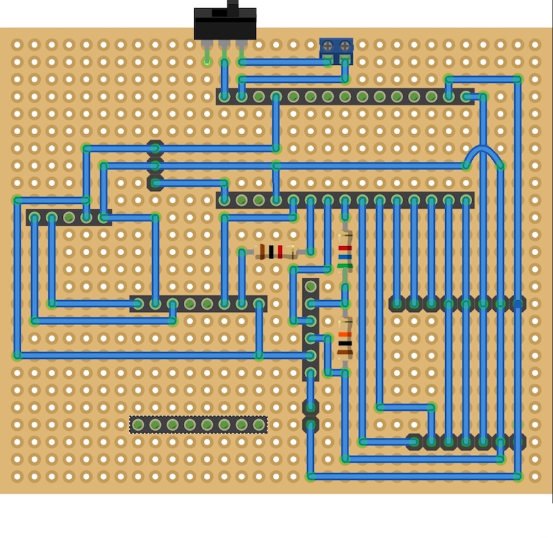
The main elements present on the control board are the following:
- Arduino Nano ver. 3.0.
- DFPlayer Mini MP3 Player.
- Adafruit Mono 2.5W Class D Audio Amplifier.
- Bluetooth module HC-05.
With protoboard:
With 7x9 cm double-sided PCB board:
The elements present in the vertical structure are the following:
- Speaker 4 Ohms and 3W of power.
- Adafruit 1.44 "Color TFT LCD Display with MicroSD - ST7735R.
- 12 LEDs RGB WS2812B 5050 Ring.
The vertical structure that will contain the speaker and the visual elements (ring of LEDs and TFT) I made using elements of Makeblock. They are the following:
- 1 plate 7x9 B (Makeblock).
- 1 beam 0824 176mm or the size you want (Makeblock).
- 2 plates of 3x6 (Makeblock).
- 4 spacers of 20 mm in length for M4 bolts.
- Screws.
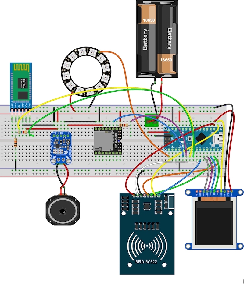
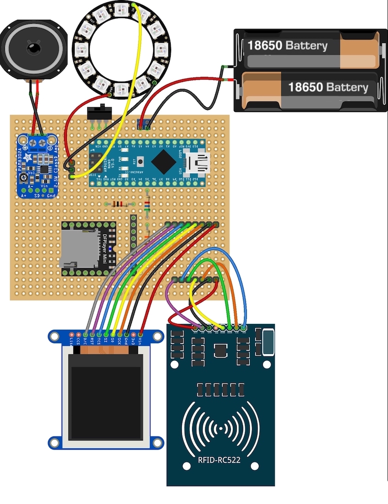
Finally we will connect the elements present in the vertical structure (speaker, LEDs Ring and TFT) and the RFID-RC522 module to the control board by dupont cables of 20 cm. We will also add the power supply which will be supplied by 2 Panasonic NCR18650B rechargeable Li-Ion batteries (3400 mAh, 3.7V) located inside a battery compartment with power cable.
With protoboard:
With 7x9 cm double-sided PCB board:
NOTE: In the diagram I have expressly suppressed the HC-05 bluetooth module in order to see the connections to the RFID-RC522 module and the 1.44 "TFT.
The final result is shown in the following images (PCB board version):
For our project we will need MIFARE Classic® 1K - 13.56MHz RFID cards that on one hand will serve to give the instructions to the robot and on the other hand to make and verify the path of the robot on the board.
We will divide the cards into 2 groups:
Movement cards / actions
- Card for the move forward.
- Card for the move back.
- Card for the movement to turn left.
- Card for the movement to turn to the right.
- Card for the action to reset the movements.
- Card for the action of executing the movements.
Board cards
- Card that identifies the start of the journey on the board.
- Card that identifies the end of the route on the board.
- Cards that mark the route between the starting point and the end point.
In all the cards of movements and actions it will be necessary to know the internal identifiers that they have, but of the board cards it will only be necessary to identify the one that marks the end of the route. These identifiers later we will have to put them in the programs that we will load both in the control board and in the program that is loaded in the Escornabot.
To know the identifiers of the cards, it will be sufficient to load the library of Miguel Balboa (https://github.com/miguelbalboa/rfid) into the Arduino IDE and open the example program called READNUID (remember to change the pins #define SS_PIN 10 and #define RST_PIN 9 to the values #define SS_PIN 7 and #define RST_PIN 6).
Once the library is installed and the program loaded on the Arduino Nano of our control board, we will open the Arduino IDE serial monitor. We will bring the different cards closer to the RFID-RC522 module (in total we have to identify 7 cards).
As we identify each card we will tag it and save its ID in hexadecimal format.
The cards that are in the board must be hooked, for this we will use double-sided tape putting only the length of tape needed so that the card can be removed and put with ease.
AUDIOSFor the different locutions present in our project we will use 15 MP3 files that we will record in the MicroSD card to later insert it in the MP3 player.
In my case I have used a Web page (http://www.fromtexttospeech.com/) where writing the text and selecting the language generates the corresponding MP3 file although you also have the option to record these locutions yourself.
Once we have the 15 MP3 files we will name them as shown below and we will record them in the root of the MicroSD card (to the right of each file you can see the audio that will be heard):
  0001.mp3: "Left"
  0002.mp3: "Right"
  0003.mp3: "Advance"
  0004.mp3: "Go back"
  0005.mp3: "Run"
  0006.mp3: "Reset"
  0007.mp3: "Turning to the left"
  0008.mp3: "Turning to the right"
  0009.mp3: "Moving forward"
  0010.mp3: "Going back"
  0011.mp3: "started!
  0012.mp3: "Wow, I think I've lost myself, are we going to try again?
  0013.mp3: "We have finished! You have done great!"
  0014.mp3: "Wow, I have not reached the end, do we try again?
  0015.mp3: "Stopping the robot and resetting movements"
Now we have to pair our bluetooth control board (which has the HC-05 module) and the Escornabot (which has the HC-06 module). Between them, bidirectional communication will take place. On the one hand the control board will send the instructions to the robot and on the other hand the Escornabot will tell you the route it is taking and if it is running correctly checking the cards present on the board.
AT commands for the HC-06 module:
AT commands for the HC-05 module:
NOTE: The HC-05 module must be in "full-AT" mode. To enter "full-AT" mode, pin 34 must be at HIGH (3.3V) level when we connect the module and keep that level HIGH throughout the process in which we are sending the AT commands.
NOTE: The detected address of the HC-06 module appears in bold. Therefore you will have to change this code for the one that comes to you when making the detection.
LOADING THE PROGRAMS ON THE CONTROL BOARD AND ON THE ESCORNABOTThe libraries that use the programs and that we will have to download and install in the Arduino IDE are the following:
https://github.com/miguelbalboa/rfid
https://github.com/adafruit/Adafruit-GFX-Library
https://github.com/adafruit/Adafruit-ST7735-Library
https://github.com/adafruit/Adafruit_NeoPixel
https://github.com/DFRobot/DFRobotDFPlayerMini/archive/1.0.3.zip
Let's see the modifications that we have to make in the two programs before loading them in the different Arduinos.
Control board program
In the code of the control board we will have to put the 6 identifiers of the movement and action cards. For this we will download the specific program from the control board of the following link:
https://github.com/avilmaru/Escornabot_proyecto_discapacidad_visual/tree/master/placaDeControl
Once downloaded we look for the code that is shown below and we will put the identifiers that we have previously scanned:
**************************************************************************
* Card identifiers
**************************************************************************/
// NOTE: Change by the codes of your cards (6 cards are necessary)
byte tarjetaGirarIzquierda[4]  = {0x71, 0x9C, 0x07, 0x01};
byte tarjetaGirarDerecha[4]    = {0xB4, 0xBD, 0xD9, 0x13};
byte tarjetaAvanzar[4]         = {0x01, 0xB5, 0x9A, 0x00};
byte tarjetaRetroceder[4]      = {0x71, 0x3C, 0x27, 0x49};
byte tarjetaEjecutar[4]        = {0xC3, 0x5B, 0xED, 0x16};
byte tarjetaResetear[4]        = {0x66, 0x7A, 0xCA, 0x1F};
NOTE: You have to replace the codes shown in the previous example with the codes of your cards.
Escornabot program
In the Escornabot program we will only have to modify the configuration file Configuration.h in order to add the identifier of the end-of-travel card and, on the other hand, to define the SS and RST pins of the RFID-RC522 module, if you have done so as explains the tutorial will be the D10 and A1.
For this we will download the modified official firmware Escornabot from the following link:
https://github.com/avilmaru/Escornabot_proyecto_discapacidad_visual/tree/master/escornabot-1.4.3
Once downloaded we look for the code that is shown below and we will put the required information:
//////////////////////////////////////////////////////////////////////
///// MFRC522 RFID
//////////////////////////////////////////////////////////////////////
#define USE_MFRC522 true
#define CHECK_RFID_CARDS_UNTIL_END_POINT true
#define MFRC522_SS_PIN  10
#define MFRC522_RST_PIN A1
// End of travel RFID card identifier
// NOTE: Change by the code of your card
#define UID1 0x11
#define UID2 0x3F
#define UID3 0x8B
#define UID4 0x02
As you can see in this case the hexadecimal code we have divided into 4 parts and each part we have assigned a variable.
NOTE: You must replace the code shown in the previous example with the code of your card.
NOTE: Pin D10 can NOT be connected to the buzzer because this pin just like pins D11, D12 and D13 are used by the SPI bus which is necessary for the operation of the RFID reader attached to the robot. In my case I used the analog pin A0 as an alternative but you can use any other that you have free. Therefore we must specify this change in the configuration file Configuration.h:
// buzzer
#define BUZZER_PIN A0
NOTE: Do not forget to put in the configuration file the rest of the configurations that you have for your robot: values of the reading of the keypad, etc., so that everything works correctly.
------------------------------------------------------------------------------------
Complete tutorial of the project:
http://www.mecatronicalab.es/escornabot-proyecto-para-ninos-con-discapacidad-visual-o-ceguera/
Video demonstration of the project:


Comments
Please log in or sign up to comment.