Hardware Required:
- Arduino UNO board
- 28BYJ-48 stepper motor (with ULN2003A driver board)
- Joystick
- 5V power source
- Bread board
- Jumper wires
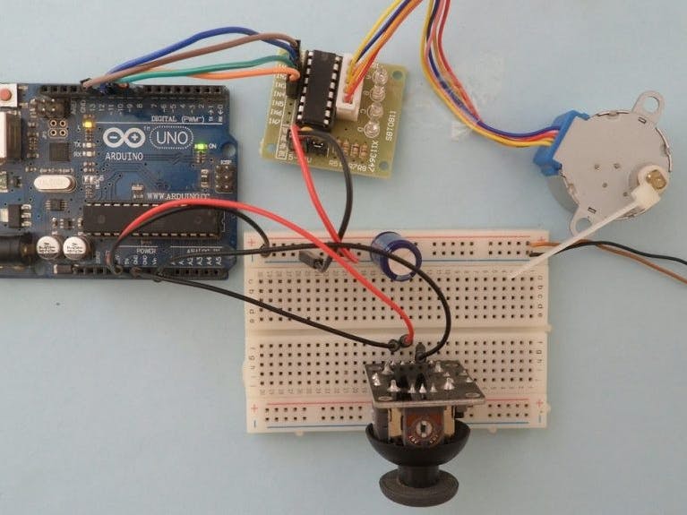
Stepper motor control with Arduino and joystick circuit:Project circuit schematic diagram is shown below (all grounded terminals are connected together).
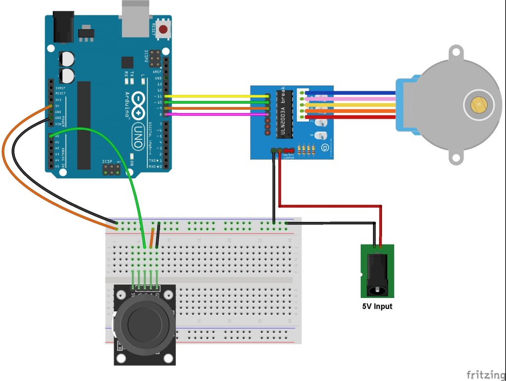
and the following image shows fritzing circuit:
The stepper motor is connected to the ULN2003A board which is supplied with external power source of 5V. The control lines (IN1, IN2, IN3 and IN4) of this board are connected to the Arduino as follows:IN1 to Arduino pin 11IN2 to Arduino pin 10IN3 to Arduino pin 9IN4 to Arduino pin 8
The joystick board has 5 pins: GND, +5V, VRX, VRY and SW where:GND and +5V are power supply pinsVRX is the X-axis potentiometer outputVRY is the Y-axis potentiometer outputSW is the push button terminal (the other terminal is connected to GND).The output of the X-axis potentiometer (VRX) is connected to Arduino analog pin A0, Y-axis potentiometer output (VRY) can also be used. The switch pin (SW) is not used in this example.Using the X-axis and the Y-axis potentiometers we can control two stepper motors independently.
"So guys if you like the project so don't forget to follow and like it"


_ztBMuBhMHo.jpg?auto=compress%2Cformat&w=48&h=48&fit=fill&bg=ffffff)


Comments
Please log in or sign up to comment.