


Hardware components | ||||||
 |
| × | 1 | |||
_ztBMuBhMHo.jpg?auto=compress%2Cformat&w=48&h=48&fit=fill&bg=ffffff) |
| × | 1 | |||
 |
| × | 1 | |||
 |
| × | 1 | |||
Software apps and online services | ||||||
 |
| |||||
Hand tools and fabrication machines | ||||||
 |
| |||||
I have a lot of rubik’s cubes. Some are big; some are small; some cost an absurd amount of money. Two years ago, my younger brother destroyed one of my cubes by throwing it on the ground, and since then I have spent $90 on security upgrades to prevent it from happening again. But even when he’s not destroying my cubes, he’s scrambling them when I have them on display. I just want to display my cubes without having them being touched. So, I spent a month building this shelf that rings an alarm whenever you remove an item from it.
Materials:
- Strobe light + piezo buzzer
- Arduino Uno
- 4x Load cells + HX711
- I2C LCD
- 4x4 Keypad
- Wires, breadboard, and transistor
- 2x 12V power supply
Optional if you are designing your own frame
- Frame pieces
- Screws and threaded inserts
I designed my frame in tinkercad and sent the files to Justway to produce.
Justway is an affordable online manufacturing service, with services such as 3d printing, cnc machining, and sheet metal forming. To place an order on Justway, click this link to open the menu page. Select the service you are using, and click upload your design.
This will take you to this page, where you can upload your design and pick your material, color, and other special requests. Once all selections have been made, submit your request and wait for it to be approved. Once approved, pay for the order and wait for the parts to arrive.
When I first used Justway for my 3d printed parts, I received an email shortly after the order about a design flaw in one of my models. The production team asked me if I wanted to continue with my original design or a modified version they had created. I opted for the original design because it wasn’t a major issue.
When I unboxed the parts, I was surprised by not only the quality and dimensional accuracy of the parts, but also the fact that I received extras for a bulk order presumably in case of shipping damage.
You can design your own frame, but if you want to use my frame, it is linked here.
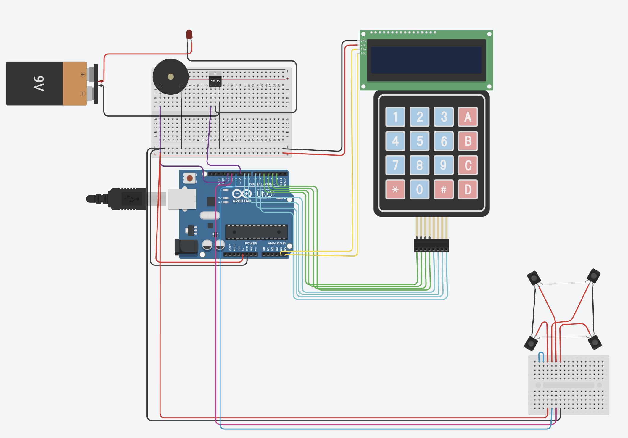
This is a diagram with all the wire connections. It's a bit overwhelming, so let's break it down.
KeypadandLCD
Using an I2C LCD, connect the ports as listed below and shown in the diagram
- VCC to 5V(ideally through breadboard)
- GND to GND(ideally through breadboard)
- SDA to A4
- SCL to A5
Using a 4x4 keypad, connect the ports as listed below and shown in the diagram
- Row 1 to 5
- Row 2 to 4
- Row 3 to 3
- Row 4 to 2
- Column 1 to 9
- Column 2 to 8
- Column 3 to 7
- Column 4 to 6
LoadCells
Tinkercad Circuits does not have a HX711, so I used a breadboard in the diagram.
Using four load cells and a HX711, connect the ports as listed below and shown in the diagram
- Place four load cells in corners of shelf
- Connect adjacent black and white wires
- Connect two opposite(diagonal) red wires to A+ and A-
- Connect other two opposite(diagonal) red wires to E+ and E-
- DO NOT CONNECT B+ AND B-
- VCC to 5V
- GND to GND
- DT to 12
- SCK to 11
StrobeLight and Buzzer
Connect Piezo's + to pin 13 and - to GND
Connect 12V power supply to strobe light through a mosfet transistor
- Gate to 10
- Drain to ground of power supply
- Source to negative of strobe light
- power of power supply to power of strobe light
I have included example code in this project. Note that the calibration factor is for my load cells. You will have to calibrate yours by yourself using the calibration example in the HX711_ADC library.


_3u05Tpwasz.png?auto=compress%2Cformat&w=40&h=40&fit=fillmax&bg=fff&dpr=2)
Comments
Please log in or sign up to comment.