


Hardware components | ||||||
| × | 1 | ||||
 |
| × | 1 | |||
 |
| × | 1 | |||
 |
| × | 1 | |||
Software apps and online services | ||||||
 |
| |||||
We take a look at a very interesting GitHub repository that enables video recording on the ESP32-CAM board. A video is nothing but a series of carefully timed images, and this sketch is based on that. The team have also added FTP functionality to the sketch which means that you can retrieve the files remotely, over the same WiFi network, without having to retrieve the microSD card.
The video above covers everything you need to know and also explains how to use the FTP feature.
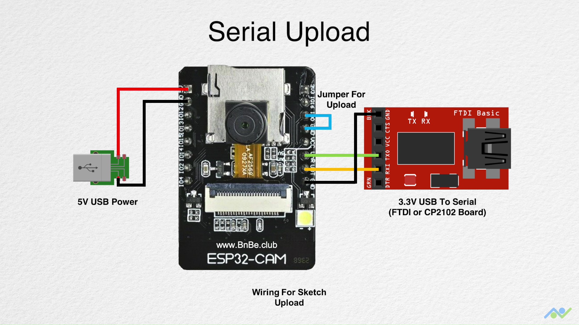
Step 1: Gather the ElectronicsThe ESP32-CAM board already contains the camera module, and microSD card slot that we need for this sketch. In addition to this, you will need a microSD card, a microUSB breakout board (optional), and also a USB to serial converter to upload the sketch.
Step 2: Edit & Upload the SketchYou can download the sketch using the link at the bottom of this post.
The ESP32-CAM board does not have an onboard USB connector so you need to use an external USB to serial converter to upload the sketch. You can use the wiring connections shown above but make sure that the USB to serial converter is connected in the 3.3V mode.
It is recommended to use an external 5V supply to power the board, particularly if you are using an FTDI breakout board. For the external 5V supply, a simple USB breakout board will do just fine. There has been some success in powering the board directly from the CP2102 breakout board so you can try that first. The board also has a 3.3V power pin if needed.
The jumper is needed to put the board in the download mode. Once you have everything connected, power up the board, open a serial terminal (Tools->Serial Monitor) with a baud rate of 115, 200 and press the reset button. You should obtain the debug output as shown in the image and this will indicate that everything is working as expected.
You can now upload the code by pressing the upload button. Wait for it to complete, then remove the jumper and press the reset button to obtain the final output which will indicate that the recording has started.
Step 3: Disable Flash by Modifying the BoardThis bit is optional but you can disable the onboard LED flash by lifting a transistor pin on the board. Since the LED flash control line is shared with the microSD card, it will light up and toggle when the microSD card is being accessed. The GitHub page shows you how to make this change and it is completely reversible so you can always enable it later.
If you don't feel like making this change then you can simply block the LED flash if it is causing a disturbance.
Step 4: Control the BoardThe board will print out the IP address once it connects to the WiFi network. You can type this into the web browser to access the control pages. The sketch also associates the hostname desklens.local to the board and you can type this into the address bar instead of the IP address. The pages contain hints to get you started and you can even specify the recording settings directly into the address bar.
The sketch also creates a basic FTP server and you can access the microSD card contents by using this feature. It is recommended to use a FTP client for this and the video walks you through the steps of using FileZilla.
Here are some relevant links in case you would like to learn more about us. Thank you for your support!
- YouTube: https://www.youtube.com/channel/UCbWiK1A5RqAugSquBHuyBdA
- BnBe Website: https://www.bitsnblobs.com/
- Instagram: https://www.instagram.com/bnbe.club/
- Facebook: https://www.facebook.com/BnBe.club
- Twitter: https://twitter.com/bnbe_club
Comments
Please log in or sign up to comment.