


Hardware components | ||||||
 |
| × | 1 | |||
 |
| × | 1 | |||
After adding sound to the original pinball project (see this Arduino-controlled pinball machine project and this pinball sounds and music project) the pinball machine became a favorite whenever friends and family came over. However, I noticed that when they played, they mentally kept track of their scores to see who did the best. This made me think that display system that would keep track of high scores and bonus values would be a great addition. Little did I know, it would be so involved.
ProcessTo begin with, I decided to use a Raspberry Pi Touchscreen Display mounted on the front of the machine. This would both display information and allow users to enter their names for addition to the high score values. To power this, I decided to use a Raspberry Pi 3 board. I also decided to program the Pi in Python. Prior to this, I had done all of my programing in Visual Basic and various forms of C. I had also never worked with a Raspberry Pi before.
At first things seemed to go easy. I got the Raspberry Pi up and running. I soon learned enough Python that I was able to use Tkinter to handle display items and I learned how to get serial communication from the Arduino board. I did this by plugging the USB cable from the Arduino into one of the USB ports on the Raspberry Pi. To the Arduino code, I added the following lines whenever there was a change in score.
Serial.print(Score);
Serial.print(", ");
Serial.print(Roll);
Serial.print(", ");
Serial.print(Pop);
Serial.print(", ");
Serial.print(Target);
Serial.print(", ");
Serial.println(Ball);
This is how the Raspberry Pi would learn the new Score, Roll Over value, Pop Bumper value, Target value and what Ball you are on. The Roll Over value, Pop Bumper value and Target values all increase when each of the different ones has been lit up. For example, once all of the Pop Bumpers have been lit, the Pop Bumper value increases and the Pop Bumper lights are then shut off. One difference was when the game was over. The code shown above was again sent, but the value for the Ball was -1 instead. This informs the Raspberry Pi that the game is over and that it should check to see if a high score was achieved. The full updated Arduino code has been added below along with the Raspberry Pi Code.
While it was straightforward to get both the serial communication and the display aspects to work separately, I had a lot of trouble getting them to work together. Python is simply not very good at handling interrupts compared to programs like Visual Basic. (Visual Basic has plenty of it own annoyances.) Whenever serial communication is sent from the Arduino, I wanted the Raspberry Pi to immediately stop whatever it was doing and display the current score values. To do this, I eventually figured out how to make a thread that would run the serial check in background and then execute a display change when data was present. The comments in the attached code should make most of this clear.
To handle the display aspects, I set up a number of labels and buttons in Tkinter. For labels where the text was going to change in parts of the program, I set up the text variable as a StringVar(). This way, when I changed the value of that variable, the label would change. When displaying these labels and buttons, I did so using the .grid(row = x, column=y) positioning element. This generally allowed me to keep everything aligned fairly well. Sometimes I also needed to the .columnspan attribute of the .grid element, as well. This is useful when you have a long line of text beneath a number of smaller columns above. Sometimes during the program, I need some of these labels to disappear. This is accomplished using a .grid_forget() command. (Note: it is important to keep the label declaration and the .grid(row = x, column=y) commands on separate lines if you are going to use .grid_forget(). While you can put them on together on one line, for whatever reason, a .grid_forget() command issued later won't work. This annoyance took quite a while to figure out.)
In order to save the high scores, I used a simple text file that the program rewrites every time a new high score is added. When the program starts, it loads this file to get these values initially into memory. The file consists of 10 sets of 3 lines containing Dates, Names and Scores. The first 5 sets are all-time highs, while the next 5 are daily highs. When the file is read when the program opens, it checks the last five if the scores are from the current date. If not, the scores are erased.
When I bought the Raspberry Pi display, it mentions that you can download a virtual keyboard for it. This was a major disappointment. Unlike a cell phone's keyboard, this virtually keyboard doesn't pop up when you need it. It seems it only works when both it and the program you are using it with are visible on your screen at the same time. Since I am running my Python program in full screen mode, I can't use the virtually keyboard to enter high scorer names. I did look into other virtual keyboards, but I couldn't find one that worked with a Python program. Consequently, I instead made my own virtual keyboard by making a lot of small buttons, each with its own letter on it. Fortunately, this worked quite well.
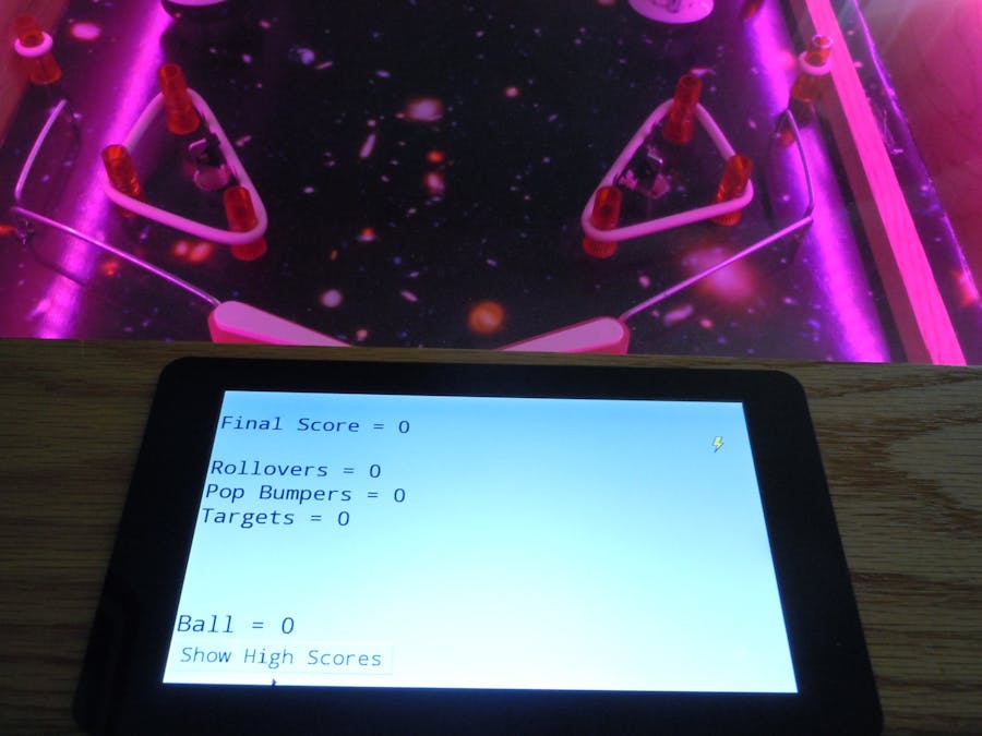
When the program is loaded, it first displays the following screen:
The player can then either begin playing or hit the button to display the high scores. If he begins playing, the following screen appears with the scores and point values being constantly update as play continues.
If the player at any time hits the high score button, he gets the following screen.
The daily high screen is basically the same, but with a different heading.
When a player gets at high score, the following screen appears, which allows him to input his name.
MountingMounting the display took some good carpentry skills. First, you'll want to follow the instructions that come with the screen on how to mount the Raspberry Pi to it. It should look like the picture below when done.
Mounting this assembly to the pinball machine isn't trivial. There are three different thickness levels on the unit. The outer edge of the screen is the thinnest. I was content to leave this proud of the surrounding wood since it is so thin. The thickest part of the assembly is where the Raspberry Pi is mounted. This needed to go all the way through the wood so that cables could be attached. When I built the pinball machine, I used pocket screws to build the frame. This was fortunate in that I was easily able to remove the frame piece closest to player so that it could be worked on. I first drilled a couple of pilot holes through the piece and then used a jig saw to cut out an approximately 3 x 3.5" hole in the wood. It doesn't have to be exact, since you won't see if from above. When you place the assembly in the hole, you will see that the last thickness layer, which has the mounting screw holes that you will need. This needs to be recessed to make the screen look good. You can't just make a hole for this layer, since you will need some wood to attach the mounting screws to. To make the recess, I cut ¼ inch sheet of plywood with a square hole in it to use as router guide. I then used a straight router bit with a collar to make the recess. If you've never done this, you will find plenty of videos by searching "router collar". I suggest you practice on a scrap piece of wood before you do it on your actual piece. In the pictures below, you will see the router guide in place with the recess already cut and a picture of the router, collar combination that I used.
To complete the mounting process you need to drill some holes in the recessed area for the screws. You will need to buy some #4 screws that are 1 inch long. You'll also need some #6 and #8 washers. To mark where to drill the holes, I simply put some white toothpaste on the screw holes on the screen. When I then put the assembly in its proper place, enough toothpaste transferred to the wood that I could easily tell where to drill. Now just first put a #6 washer on the screw, followed by a #8, pass the screw through the wood and screw it into the screen. When you are all done it should like the picture below when shown with the pinball cover open. I should point out that the white band running all the way across the picture is an LED lighting strip I used during the original pinball build to jazz it up. Also, the Raspberry Pi power cord shown in this photo has now been replaced with an angled cord in order to allow the pinball cover to close correctly.
All of the power for the pinball machine runs to a power strip mounted on the back. When I turn on the power, the Raspberry Pi loads up normally and then I double tap on an icon that I made which runs the Python program.
To make an icon of the program that will run when double tapped, first open the file manager and go to the directory below.
/usr/share/applications
Here you will find a number of .desktop files. Right click on the Python file and select text editor. Copy all of the text that appears. Go to the desktop, right click on it and select Create New, Empty File. Enter the name for your icon. When that icon appears, right click on it and select Text Editor. Paste the text you copied into the editor. Change the Name entry to match the name of your icon. Then go to the end of the line that begins with "Exec=
" Place the full file name there. For example, my line looks like the following with "/home/pi/Documents/Pinball/Pinball.py
" being the address of my pinball Python file.
Exec=/usr/bin/pyton3.4 /home/pi/Documents/Pinball/Pinball.py
Now save the file. If you double click on this icon now, the terminal program should open and automatically run your pinball program.
If you want the program to automatically run at startup, you can find some ways to do this at https://www.dexterindustries.com/howto/run-a-program-on-your-raspberry-pi-at-startup/
Like I said earlier, this was a lot more work that I expected. Still, people who have now played the game find it to be a noticeable improvement in the enjoyment level of the game. I know that several people have been inspired by my previous efforts to build an Arduino pinball machine. Hopefully this posting will inspire some of you to add a Raspberry Pi Touchscreen to your projects, whatever they may be.


Comments
Please log in or sign up to comment.