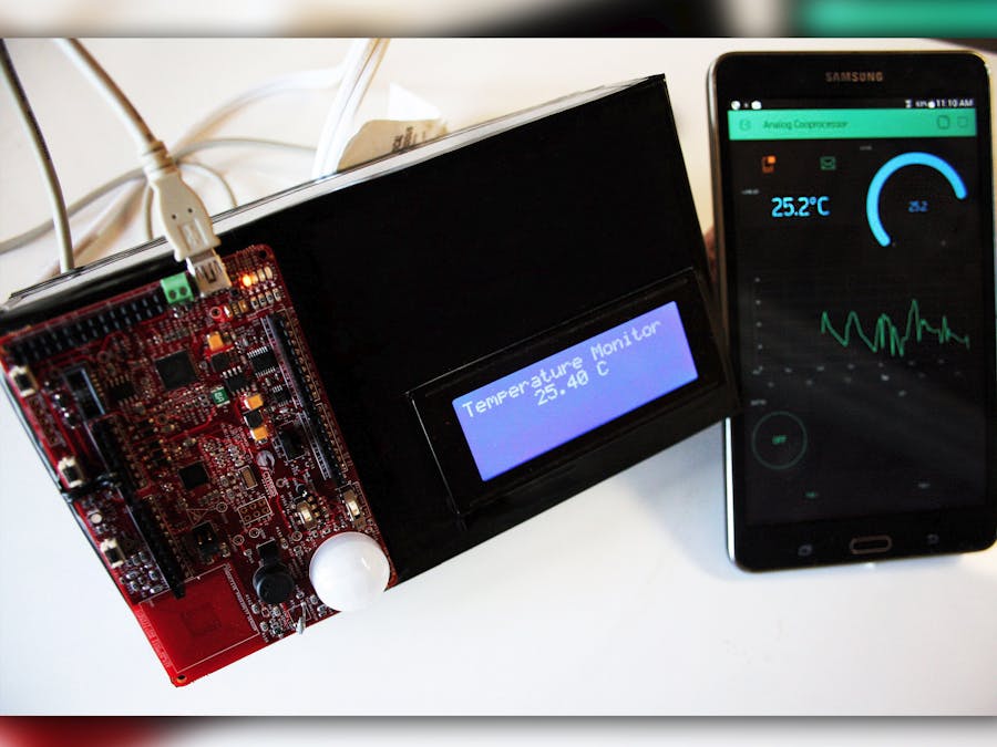
This project is based on the sensors of the PSoC analog Cooprocesor, using the thermistor to take the temperature of your home and using the PIR sensor to detect movement. a communication between the psoc and ESP8266 allows you to upload data to the Internet using Blynk , this makes it possible to send alerts to the phone and an email every time motion is detected, also in the graphical interface will be able to know the Temperature value.
INTRODUCTIONSometimes and as in a previous project, it is necessary to monitor your house in a practical way, with the progress and the appearance of new technologies it becomes more and more easy to achieve this. For this project I will use the one that is one of the easiest solutions to upload data to the internet and be able to view it on your smartphone, Blynk.
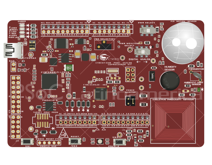
Through a PSoC CY8CKIT-048, measurements of variables of temperature and movement will be taken, which with the help of a WiFi module (ESP8266) and a serial communication will be uploaded to blynk servers to be displayed on a smartphone.
CONFIGURING PSoC Analog CooprocessorThe first thing to do is to configure the PsoC correctly so that it is able to read the temperature and detect movement, thus also displaying the values on an LCD.
To make the schematic diagram of the projects it's necessary to know that is based on the PIR sensor project, this is in the examples of PSoC Creator. In this way what is done is to correctly configure the sensor and add the rest of functionality to the same project.
We start by adjusting the gain of the amplifier for the response signal of the PIR sensor, it is changed from its default value to the maximum value of 32, this after performing several tests of operation of the PIR sensor. With this you have the complete functionality of the PIR sensor, observing its response in an LED.
Now it's time to add the temperature sensor. As the card has a thermistor to measure the temperature, you begin to make adjustments to the program. For proper operation the thermistor requires an ADC which obtains the voltage values of both the sensor and the reference resistor. Thanks to Scan ADC you can have several ADC channels, as the PIR sensor uses the first two channels, two more are added for the operation of the thermistor sensor, the ADC reading configuration is left by default. Next is added the thermistor block that performs the conversion through a LookUpTable (LUT) of voltages to resistors and resistors to temperature.
Reviewing, it is not possible to add an LCD to the project in a normal way, since the use of the sensors occupy most of the available pins, therefore the decision is made to use an LCD with an I2C interface with the help of a library That was adapted (PSoC Latin America) a while ago for PsoC. This makes it necessary to use an I2C SCB block, which is set up correctly to work with the LCD. The operation of the LCD is almost the same as a normal LCD, only saving on the use of pins, only it needs 2 pins (SDA - SCL) for its operation.
The objective of the project is to upload these two data to the internet, it is mandatory to have a module that allows the connection to the internet, first the serial communication is implemented in the PSoC, for this a UART block is added and configured at 9600 baud, Establish a format for sending data, the decision is made to send the data with identifiers, the identifier A for temperature and the identifier B for the state of the PIR sensor. For example, if the temperature of the moment is 25.63º and the state of the PIR sensor is 0 (0 = not triggered 1 = triggered) then the data to be sent by serial are A2563B0, in this way it is easy to separate these values in the receiver module.
Finally the sending of data does not need to be done so fast, it is estimated that it is time to obtain a correct reading of temperature every 300mS, the Timer is implemented and it is associated with an interruption that is in charge of taking the Value Temperature and the PIR sensor and send it through the selected format to the receiver module.
The code used for the PSoC is the following, (most routines are adaptations of the base routines of the PIR sensor project):
/* Header File Includes */
#include <project.h>
#include <stdio.h>
#include <stdlib.h>
#include "LiquidCrystal_I2C.h"
#define LED_ON                      (0u)
#define LED_OFF                     (1u)
#define MOTION_DETECTED             (1u)
#define MOTION_NOT_DETECTED         (0u)
#define THREE_FEET                  (3u)
#define TEN_FEET                    (10u)
#define TWENTY_FEET                 (20u)
#define ADC_CHANNEL_PIR             (0u)
#define SENSOR_RAW_INITIAL          (0)
/* EzI2C Read/Write Boundary */
#define READ_WRITE_BOUNDARY         (1u)
/* High and low thresholds for the motion detection are determined
	through experiments */
/* High Threshold for 3 feet detection (80% of positive peak count) */
#define PIR_WINDOW_HIGH_3FT         (1200)
/* Low Threshold for 3 feet detection (80% of negative peak count) */
#define PIR_WINDOW_LOW_3FT          (-1200)
/* High Threshold for 10 feet detection (80% of positive peak count) */
#define PIR_WINDOW_HIGH_10FT        (600)
/* Low Threshold for 10 feet detection (80% of negative peak count) */
#define PIR_WINDOW_LOW_10FT         (-600)
/* High Threshold for 20 feet detection (80% of positive peak count) */
#define PIR_WINDOW_HIGH_20FT        (1200)
/* Low Threshold for 20 feet detection (80% of negative peak count) */
#define PIR_WINDOW_LOW_20FT         (-1200)
/* Structure that holds the sensor values                                        */
/* Use __attribute__((packed)) for GCC and MDK compilers to pack structures      */
/* For other compilers use the corresponding directive.                          */
/* For example, for IAR use the following directive                              */
/* typedef __packed struct {..}struct_name;                                      */
typedef struct __attribute__((packed))
{
   uint8 detectionDistance;      	/* PIR detection distance */
	int16 sensorRawValue;        	/* ADC result */
	int16 highThreshold;		    /* High threshold for motion detection */
	int16 lowThreshold;			    /* Low threshold for motion detection */
   uint8 motionDetected;		    /* Motion detection flag */
}pir_sensor_data;
/* Function Prototypes */
void InitResources(void );
CY_ISR(TIMEBASE_ISR);
/* Declare the i2cBuffer to exchange sensor data between Bridge Control Panel (BCP) and PSoC Analog Coprocessor */
pir_sensor_data i2cBuffer = {THREE_FEET, SENSOR_RAW_INITIAL,
                            PIR_WINDOW_HIGH_3FT, PIR_WINDOW_LOW_3FT,
                            MOTION_NOT_DETECTED};
/*******************************************************************************
* Function Name: main
********************************************************************************
*
* Summary:
*  This function initializes all the resources, and in an infinite loop, performs tasks to measure all the sensor
*  parameters from sensors and to send the data over I2C.
*
* Parameters:
*  None
*
* Return:
*  int
*
* Side Effects:
*   None
*******************************************************************************/
/*****************************************
   inicializacion de componentes del termistor
   ******************************************/
   int32 vTherm,vRef; // variables correspondientes a los voltajes de referencia y termistor
   int32 Termresis,Termtemp; // variables correspondientes a resistencia y temperatura de termistor
   float TermistorResis,TermistorTemp;// variables para la corrección del formato de resistencia y temperatura
   char str[12];// variable para imprimir
   int16 filterOutputVref=0;
   int16 filterOutputVth=0;
   /* Variables to hold calculated resistance and temperature */
   int16 thermistorResistance, temperature;
   int16 estadopir=0;
   uint32_t Addr = 0x3F;
   int pir = 0;
CY_ISR(leerTemp)
{
       sprintf(str,"A%dB%d",temperature,estadopir);
       UART_UartPutString(str);
       sprintf(str,"%.2f C",(temperature/100.00));
       setCursor(6,1);
       LCD_print(str);
       if(estadopir==1)
       {
           setCursor(0,3);
           LCD_print("     Movement!!");
       }else{
           setCursor(0,3);
           LCD_print("                    ");
       }
       // ADC_StartConvert();
       Timer_Stop();
       Timer_Start();
       LED_Prueba_Write(!LED_Prueba_Read());
}
int main()
{
   UART_Start();
   Timer_Start();
   isrLeerTemp_StartEx(leerTemp);
   I2C_Start();
   LiquidCrystal_I2C_init(Addr,20,4,0);
   begin();
   LCD_print("Temperature Monitor");
   setCursor(0,2);
   LCD_print("     PIR : ");
   LCD_print("OFF ");
   setCursor(0,2);
	/* Sensor raw value */
	int16 sensorRawValue = 0;
	/* Motion detection thresholds */
	int16 highThreshold = PIR_WINDOW_HIGH_3FT;
	int16 lowThreshold = PIR_WINDOW_LOW_3FT;
   /* Variable that stores the previous detection distance, used for checking if
       the detection distance is changed by the master(BCP) */
   uint8 prevDetectionDistance = THREE_FEET;
   /* Variable to store the status returned by CyEnterCriticalSection() */
   uint8 interruptState = 0;
   /* Enable global interrupts */
   CyGlobalIntEnable;
   /* Initialize all the hardware resources */
   InitResources();
   /* Infinite Loop */
   for(;;)
   {
       /* If the master(BCP) changed the detection distance, change the second stage
           amplifier (PGA) gain and the thresholds for the required detection distance*/
       if (i2cBuffer.detectionDistance != prevDetectionDistance)
       {
           prevDetectionDistance = i2cBuffer.detectionDistance;
           /* Set the required detection distance */
           switch (i2cBuffer.detectionDistance)
           {
               case THREE_FEET:
                   /* Set second stage PGA gain and thresholds that gives
                       3 feet detection distance */
                   PIRAmplifierStage2_SetGain(PIRAmplifierStage2_GAIN_1);
                   highThreshold = PIR_WINDOW_HIGH_3FT;
                   lowThreshold = PIR_WINDOW_LOW_3FT;
                   break;
               case TEN_FEET:
                   /* Set second stage PGA gain and thresholds that gives
                       10 feet detection distance */
                   PIRAmplifierStage2_SetGain(PIRAmplifierStage2_GAIN_2);
                   highThreshold = PIR_WINDOW_HIGH_10FT;
                   lowThreshold = PIR_WINDOW_LOW_10FT;
                   break;
               case TWENTY_FEET:
                   /* Set second stage PGA gain and thresholds that gives
                       20 feet detection distance */
                   PIRAmplifierStage2_SetGain(PIRAmplifierStage2_GAIN_32);
                   highThreshold = PIR_WINDOW_HIGH_20FT;
                   lowThreshold = PIR_WINDOW_LOW_20FT;
                   break;
               default:
                   /* Set second stage PGA gain and thresholds that gives
                       3 feet detection distance */
                   PIRAmplifierStage2_SetGain(PIRAmplifierStage2_GAIN_1);
                   highThreshold = PIR_WINDOW_HIGH_3FT;
                   lowThreshold = PIR_WINDOW_LOW_3FT;
                   break;
           }
       }
       /* Check if ADC data is ready */
       if(ADC_IsEndConversion(ADC_RETURN_STATUS))
       {
           /* Read ADC result */
           sensorRawValue = ADC_GetResult16(ADC_CHANNEL_PIR);
           /* Check if motion is detected */
           if((sensorRawValue > highThreshold) ||
              (sensorRawValue < lowThreshold))
           {
               /* Once the motion is detected, the RGB LED is driven with RED color for 5s
                  and the motion detected variable in I2C buffer is latched to '1' for 5s.
                  If another motion is detected before 5s elapsed the timer is restarted
                  to maintain 5s time window */
				/* Stop the timer */
               Timebase5s_Stop();
				/* Reload the counter */
				Timebase5s_WriteCounter(Timebase5s_TC_PERIOD_VALUE);
				/* Start the 5s timer */
               Timebase5s_Start();
				/* Update the status of motion detection */
				i2cBuffer.motionDetected = MOTION_DETECTED;
				/* Turn ON the LED */
               Pin_LED_Write(LED_ON);
               estadopir=1;
               /*
               UART_UartPutChar('1');
               UART_UartPutChar('\n');
               UART_UartPutChar('\r');
               */
           }
       }
		/* Enter critical section to check if I2C bus is busy or not */
       interruptState = CyEnterCriticalSection();
   /*
       if(!(EzI2C_EzI2CGetActivity() & EzI2C_EZI2C_STATUS_BUSY))
       {
          // Update the I2C buffer
           i2cBuffer.sensorRawValue = sensorRawValue;
			i2cBuffer.highThreshold = highThreshold;
			i2cBuffer.lowThreshold = lowThreshold;
       }
	*/
		/* Exit critical section */
       CyExitCriticalSection(interruptState);
       /****************************************
       Programa termistor
       *****************************************/
       //ADC_IsEndConversion(ADC_WAIT_FOR_RESULT);// Esperar por un resultado
       vTherm = ADC_GetResult16(2);// Guardar resultado en la variable Vtherm
       //ADC_StopConvert();// Parar conversiones del ADC
       //ADC_StartConvert();//Empezar conversiones del ADC
       //ADC_IsEndConversion(ADC_WAIT_FOR_RESULT);//Esperar por un resultado
       vRef = ADC_GetResult16(1);// Guardar resultado en la variable Vref
       //ADC_StopConvert();// parar conversiones del ADC
       /* Low pass filter the measured ADC counts of Vref */
           filterOutputVref = (vRef + (32u - 1) * filterOutputVref) / 32u;
           /* Low pass filter the measured ADC counts of Vth */
           filterOutputVth = (vTherm + (32u - 1) * filterOutputVth) / 32u;
           /* Calculate thermistor resistance */
           thermistorResistance = Thermistor_GetResistance(filterOutputVref, filterOutputVth);
           /* Calculate temperature in degree Celsius using the Component API */
           temperature = Thermistor_GetTemperature(thermistorResistance);
       TermistorResis=Termresis/1000.000;// correcion del formato para la resitencia
       TermistorTemp = Termtemp/100.00;// correccion del formato para el termistor
   }
}
/*******************************************************************************
* Function Name: void InitResources(void)
********************************************************************************
*
* Summary:
*  This function initializes all the hardware resources
*
* Parameters:
*  None
*
* Return:
*  None
*
* Side Effects:
*   None
*******************************************************************************/
void InitResources(void)
{
   /* Start EZI2C Slave Component and initialize buffer */
   //EzI2C_Start();
   //EzI2C_EzI2CSetBuffer1(sizeof(i2cBuffer), READ_WRITE_BOUNDARY, (uint8*)&i2cBuffer);
   /* Enable LED timebase ISR */
   isr_Timebase5s_Start();
   isr_Timebase5s_StartEx(TIMEBASE_ISR);
   /* Start the Scanning SAR ADC Component and start conversion */
   ADC_Start();
   ADC_StartConvert();
   /* Start the Reference Buffer */
   RefBuffer_Start();
   /* Start Programmable Voltage Reference */
   PVref_Start();
   /* Enable Programmable Voltage Reference */
   PVref_Enable();
   /* Start the first stage amplifier */
   PIRAmplifierStage1_Start();
   /* Start the second stage amplifier (PGA) */
   PIRAmplifierStage2_Start();
}
/*******************************************************************************
* Function Name: CY_ISR(TIMEBASE_ISR)
********************************************************************************
*
* Summary:
*  This function implements the ISR for 5s timebase
*
* Parameters:
*  None
*
* Return:
*  None
*
* Side Effects:
*   None
*******************************************************************************/
CY_ISR(TIMEBASE_ISR)
{
  	/* Reset the motion detection flag */
   i2cBuffer.motionDetected = MOTION_NOT_DETECTED;
   /* Turn OFF the LED */
   Pin_LED_Write(LED_OFF);
   estadopir=0;
   /*
   UART_UartPutChar('0');
   UART_UartPutChar('\n');
   UART_UartPutChar('\r');
   */
   /* Stop the 5s timer */
   Timebase5s_Stop();
}
The next step is to configure the receiver module (ESP8266)
BLYNKBefore proceeding with the configuration of the receiver module it is necessary to first create the graphical user interface in blynk. In an earlier project explained in detail what Blynk's philosophy of operation, you can consult (here)
For this project of blynk a gauge was used to show the temperature in addition to a Label to show the value in numbers. Also, a graph was used to observe the changes of temperature in real time and another graph to have the history of data in time. Finally, the notification systems are added, which are notifications of the mobile, and notifications by mail, are necessary to generate the alert every time the sensor detects movement. There is also a led pilot that lights up every time movement is detected and a button to turn on and off a physical LED of the module, in order to be able to see if there is connection with the module. The terminals of the security configurations are sent to the security token necessary for the connection of the module to the internet.
You can read the QR code from blynk and review all the settings.
RECEIVER MODULE (ESP8266)Once the application is configured, it is time to program the module.
The first thing to know is that you will use the arduino IDE to proceed with programming. I recommend reading the previous project where you explain in detail the configuration and programming of the module, Here we will speak in a general way.
Remember to have the ESP card installed in arduino and the blynk library
Starting with the program the first thing to do is to place the security token and the credentials of the WiFi network to which it will connect. Then you should think about receiving the data. The serial communication of 9600 baud is implemented. The routine for reading the data in the module described in the code is capable of reading the data frame from the PSoC and separating the temperature data and the PIR sensor. Once the data is seperated, what follows is to update the graphs of blynk.
It is necessary to think that some of the functionalities of blynk have a limit as far as the time of update of the data, therefore must be generated a routine of timer that is able to send the data to the server of blynk from time to time.
After this, we will update the blynk gadgets.
 #define BLYNK_PRINT Serial    // Comment this out to disable prints and save space
#include <ESP8266WiFi.h>
#include <BlynkSimpleEsp8266.h>
#include <SimpleTimer.h>
// You should get Auth Token in the Blynk App.
// Go to the Project Settings (nut icon).
char auth[] = "ef3449684be14bc6bcb303a40f68f1d1";
SimpleTimer timer;
// Your WiFi credentials.
// Set password to "" for open networks.
char ssid[] = "Lilith4";
char pass[] = "AeroTallica.1";
int llaveescritura=0;
char inChar;
char num1[10];
char num2[10];
String string1="";
int val1=0;
int val2=0;
String string2="";
int i=0;
int string1l =0;
int string2l =0;
WidgetLED ledmovimiento(V2);
void myTimerEvent()
{
 if (val2==1)
 {
   ledmovimiento.on();
   Blynk.notify("Heey....!! Hay movimiento en tu casa!");
   Blynk.email("Subject: PIR Sensor", "Hay movimiento en la casa...");
 }else{
   ledmovimiento.off();
 }
}
void setup()
{
 Serial.begin(9600);
 Blynk.begin(auth, ssid, pass);
 timer.setInterval(1000L, myTimerEvent);
}
void loop()
{
 Blynk.run();
 timer.run();
   if (Serial.available()){
   //Lectura de caracteres
      inChar = Serial.read();
   //Suma de caracteres en variable string
     if(llaveescritura==1)
     {
       string1+=inChar;
     }
     if(llaveescritura==2)
     {
       string2+=inChar;
     }
     if(inChar=='A')
     {
       string1l=string1.length();
       string2l=string2.length();
       for (int a = 0; a<=string1l-2; a++)
         {
           num1[a]=string1.charAt(a);
         }
       for (int a = 0; a<=string2l-2; a++)
         {
           num2[a]=string2.charAt(a);
         }
       val1 = atoi(num1);
       val2 = atoi(num2);
       Serial.print("Val1: ");
       Serial.println(val1);
       Serial.print("val2: ");
       Serial.println(val2);
       Blynk.virtualWrite(V1,val1/100.00); //actualizando temperatura
       Blynk.virtualWrite(V3,val1/100.00);
       Blynk.virtualWrite(V0,val1/100.00);
       string1="";
       string2="";
       num1[0]='\0';num1[1]='\0';num1[2]='\0';num1[3]='\0';num1[4]='\0';num1[5]='\0';num1[6]='\0';num1[7]='\0';num1[8]='\0';num1[9]='\0';
       num2[0]='\0';num2[1]='\0';num2[2]='\0';num2[3]='\0';num2[4]='\0';num2[5]='\0';num2[6]='\0';num2[7]='\0';num2[8]='\0';num2[9]='\0';
       llaveescritura = 1;
     }
     if(inChar=='B')
     {
       llaveescritura = 2;
     }
     }
}
Remember that to program this module you have to do some hardware configurations:
To program the module uses a serial-USB interface (FT232RL) and make connections in the module as described by the image Following this you can program without problems.
HARDWAREHaving the two cards programmed you can proceed with the assembly of the Hardware:
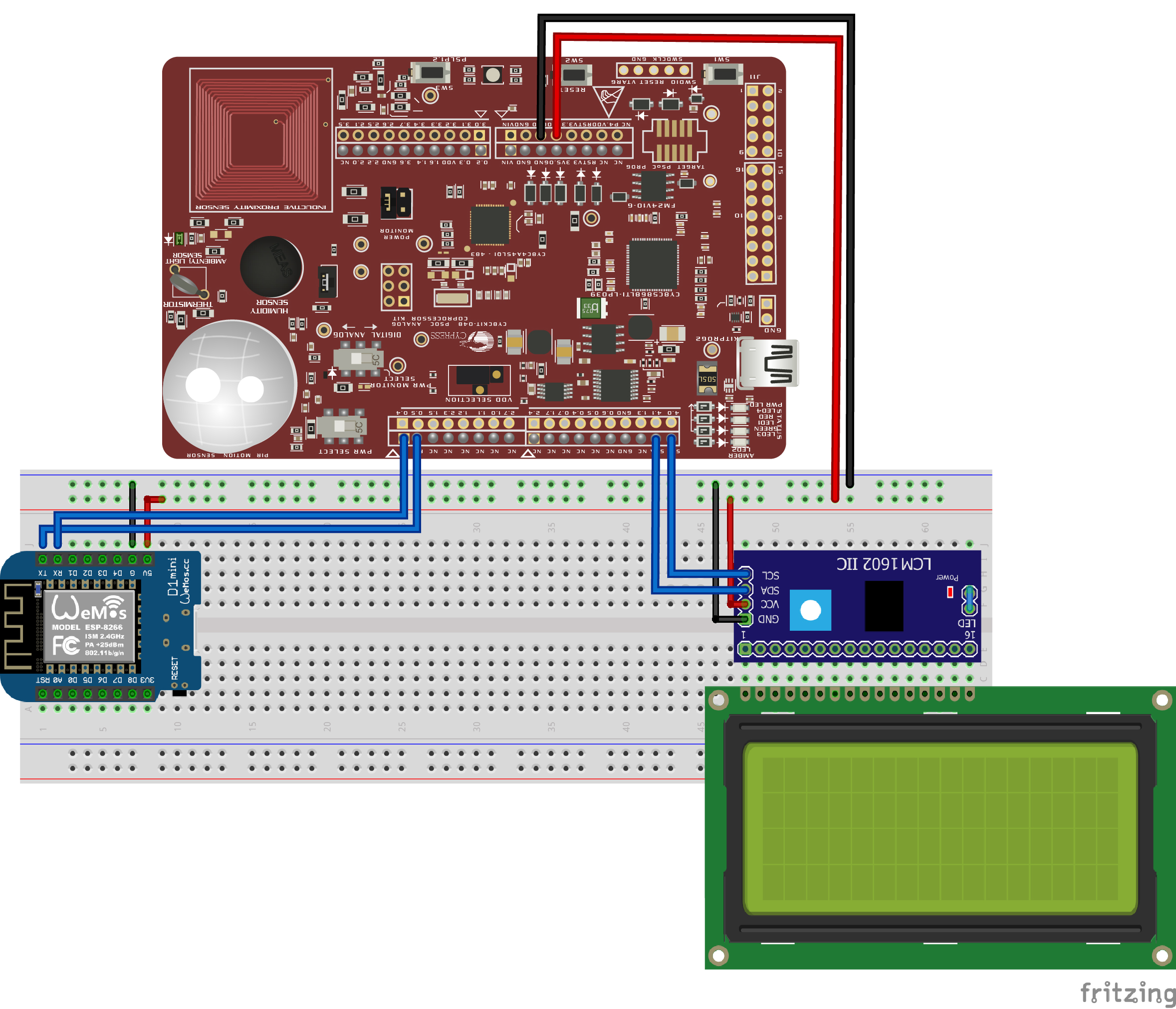
The power is obtained directly from the CY8CKIT-048 KIT, from here the feeds are taken for the ESP8266 module and the LCD, as described by the hardware assembly image.
And finally a housing is built and the components are organized so that the PIR sensor is discovered.
RESULTS
- It provides a very good application, you have to think that this same can be implemented with all the sensors in the application you want, as it is here only monitoring and security.
- In its general operation it is noticed that there is a little delay while movement is detected and the notification is activated in the cellular, due to different factors between this the connection to the server from the module.


Comments
Please log in or sign up to comment.