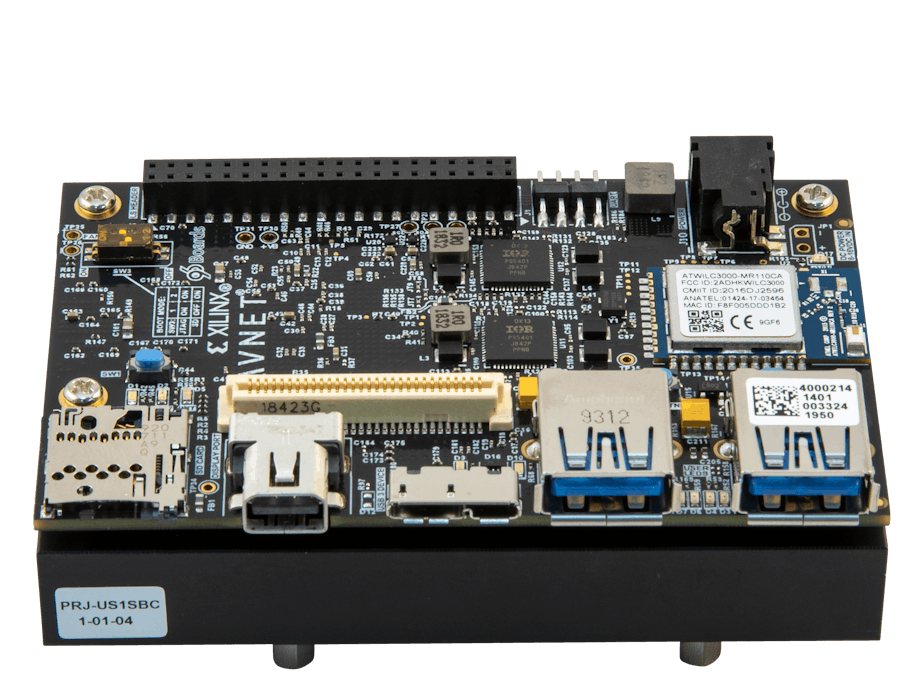
Once a ZU+ Hardware Platform is created and exported from Vivado, the next step is to create an application targeted at the platform and see it operating in hardware. This tutorial will show how to do that with the simplest of all software applications – Hello World.
If you haven't already created the ZU+ Hardware Platform for Ultra96-V2, go back to this tutorial and complete this one first.
https://www.hackster.io/BryanF/ultra96-v2-vivado-2020-2-basic-hardware-platform-6b32b8
Much of this project draws from the Xilinx Zynq UltraScale+ MPSoC Embedded Design Tutorial UG1209, adapted to the Ultra96-V2. It is highly recommended that the user refers to this document as well.
ObjectivesWhen this tutorial is complete, you will be able to:
- Import a ZU+ Hardware Platform into Vitis
- Create a standalone (bare metal) BSP
- Add a new application based on a Xilinx-provided template in Vitis
- Run the application on the Ultra96-V2 hardware
The software used to test this reference design is:
- VirtualBox Ubuntu 18.04.1 Virtual Machine
- Xilinx Vitis 2020.2
- USB-JTAG device driver
- Terminal software, such as GtkTerm
The hardware setup used to test this reference design includes:
- Host PC
- Ultra96-V2
- 96Boards 4A Power Supply
- Ultra96 JTAG/UART Pod
- Micro-USB cable
The first step is to launch Vitis and then import a hardware platform.
- Launch Vitis 2020.2.
- Select a workspace in any location of your choosing (make sure to avoid a workspace with a space in the pathname though). For convenience, this tutorial created a directory called "Ultra96_Basic_Applications" inside the Ultra96_Basic_System project hierarchy. Browse to the directory and click Open. Then click Launch.
- Close the Welcome screen by clicking the X next to Welcome on the tab.
Now we will import the ZU+ hardware platform that was designed and built during the first tutorial.
- Select File > New > Platform Project.
- Give the Platform project a name, such as Ultra96_Basic_Platform. Click Next>.
- The Create a new platform from hardware (XSA) tab should be selected. Click Browse then go to your project directory, for example
/home/training/Projects/Ultra96_Basic_System. Select the.xsa file, in this case --design_1_wrapper.xsa. Click Open. - After a moment of processing, you can see the default selections targeting
Operating system: standalone
Processor: psu_cortexa53_0
Architecture: 64-bit- The Generate boot components checkbox should be checked with the FSBL created for psu_cortexa53_0
- Click Finish
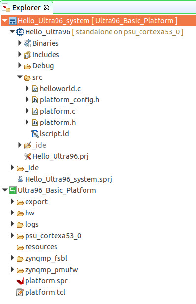
- After a short time, the ZU+ hardware platform is now visible in Explorer. With that hardware platform as the basis, we can now create applications to link against this platform.
You can also see that the FSBL, standalone BSP for A53, and the PMU firmware have all been generated, which are critical for new applications.
- If you click on the Hardware Specification tab, Vitis will show you information about the hardware platform.
You can also see the Address Maps for the A53s, R5s, and PMU processors in that same window.
Down at the bottom of the Hardware Specification, you will find the IP blocks present in the design.
The bare metal board support package for the A53, which Xilinx calls Standalone, is already created. However, we must modify it to work properly with Ultra96-v2.
DO NOT MISS THIS STEP OR YOU WILL GET NO OUTPUT!!!
- Select the Main tab.
- With Board Support Package selected under standalone on psu_cortexa53_0 on the Ultra96_Basic_Platform window, select the Modify BSP Settings button on the right-hand side.
- In the Board Support Package Settings, select standalone. Change the stdin and stdout Value to psu_uart_1. This is done to align with the Ultra96-V2’s UART Serial connection. If you want more information about why, please read this article: https://www.element14.com/community/community/designcenter/zedboardcommunity/zedboard-forums/ultra96-hardware-design-forum/blog/2021/02/17/ultra96-and-the-mystery-of-the-uarts
- Click OK.
- Build the platform by right-clicking the platform, then selecting Build Project. Note that this is NOT rebuilding the hardware. This is building those software platforms identified above, getting them ready for applications to sit on top of them. Prior to building, you'll see "Out-of-date" next to the platform name. Once the build is finished, that "Out-of-date" will go away.
This may take a minute to compile the new BSP. The progress may be seen in the Console tab.
With a Hardware Platform and BSP, we are now ready to add an application and run something on the board.
- In Vitis, select File > New > Application Project.
- Review the welcome screen and check the box if you want to skip that next time. Click Next>.
- Since we have already imported the XSA and created the BSP, the Platform page should auto-select our Platform. Click Next>.
- In the Application project Name field type in
Hello_Ultra96. Click Next>.
- The Domain should auto-select the generated standalone BSP. Click Next>.
- Select Hello World from the Available Templates field. Click Finish.
- Notice that the Hello_Ultra96 application is now visible in Project Explorer.
- Click the Hammer icon to build the application.
- Connect the Ultra96 JTAG/UART Pod to J1 and J3 on Ultra96-V2. For more information on the JTAG Pod and connecting it properly, read this blog:http://avnet.me/JTAG-UART-pod-vref
The drivers for the Avnet USB-to-JTAG/UART Pod should be automatically installed the first time you plug it in. If you are experiencing issues with your JTAG/UART Pod such as the JTAG not working or neither the JTAG or UART working, follow the two steps below
1. Manually install FTDI driver from here using "Setup executable."
2. If that fails, manually install certified drivers following these instructions.
- This next photo identifies several features on the board that you will need to access, including the BOOT MODE Switch (SW3), D1 RDY LED, D17 VIN LED, and PWR BTN (SW4).
- Set the Ultra96-V2 boot mode switch SW3 to JTAG mode as shown below.
- Plug a Micro-USB cable into the host PC and the JTAG/UART Pod. Note that a native USB port on your PC may be required by certain VMs, in which case the USB cable should be plugged directly into the PC and not a USB hub. The D1 Amber RDY LED should light.
- In the Linux VM, select Devices > USB > Xilinx JTAG+Serial to allow Linux to access the JTAG Port.
- Plug in the 96Boards Power Supply to the barrel jack J10 on Ultra96-V2. The D17 Green VIN LED should light.
- Press and release the SW4 PWR BTN (power button).
All of the following should illuminate:
- D2 Green +3.3V Power LED
- D3, D4, D6, and D7 Green User LEDs (between the two Type A USB ports)
- D9 Amber USER/Status LED
- D10 Blue USER/Status LED
- Use Device Manager to determine the COM port for the USB Serial Port. In Windows 7, click Start Control Panel, and then click Device Manager. Click Yes to confirm.
A key thing to note is that the D1 Blue DONE LED is not illuminated, meaning the Programmable Logic (PL) has not been configured.
- Open your serial communication utility for the COM port assigned on your system with settings shown below. The image below shows the GtkTerm on the Ubuntu Linux VM.
If you get the following dialog, then you may not have enabled the USB device in the Linux VM, or you may have your cable plugged into a USB hub, or you may need to manually install the driver.
GtkTerm properly connected at 115200-8-N-1.
- Right-click on the Hello_Ultra96 application and select Run As >1 Launch on Hardware (Single Application Debug).
- The tools first configure the PL. You will see the D1 Blue DONE Led light. The Launch also initializes the processor, downloads the Hello_Ultra96.elf to RAM, and then runs Hello_Ultra96. This takes a few seconds to complete, depending on the USB traffic in your system. You can follow the progress in the lower right corner of Vitis.
Vitis will download the Hello World ELF to the RAM, and the ARM A53 cpu0 begins executing the code. The application standard output is displayed in the GtkTerm.
You have now booted ZU+ Ultra96-V2 hardware!
You have a choice of two different tutorials if you'd like to continue learning.
Run the same Hello World experiment on one of the R5 processorsDevelop and run Memory and Peripheral Test applications


Comments
Please log in or sign up to comment.