

Hardware components | ||||||
 |
| × | 1 | |||
 |
| × | 1 | |||
 |
| × | 1 | |||
| × | 1 | ||||
| × | 1 | ||||
 |
| × | 2 | |||
| × | 2 | ||||
 |
| × | 3 | |||
 |
| × | 1 | |||
 |
| × | 2 | |||
 |
| × | 1 | |||
 |
| × | 1 | |||
Software apps and online services | ||||||
 |
| |||||
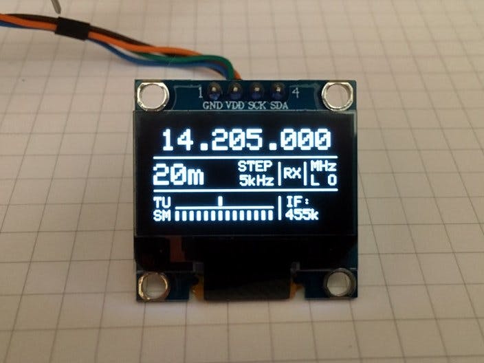
This is a project of a VFO (variable frequency oscillator) for use in DIY homebrew radio equipement such as Superheterodyne Single / Double Conversion Receivers, DCR, SDR or Ham QRP Transceivers. It has a Bargraph indicator for Signal Strenght (S-Meter) and 20 Band presets. Can be used as RF/Clock generator too. This is the new version (V.2), I updated the previous project and it includes new features.
Features:- Operation range from 10kHz to 225MHz.
- Tuning steps of 1Hz, 10Hz, 1kHz, 5kHz, 10kHz and 1MHz.
- Intermediate Frequency (IF) offset (+ or -) adjustable.
- 20 Band Presets (shortcuts) to the BCB and HAM frequencies.
- Generator funcion mode.
- RX / TX Mode Selector for use in Homebrew QRP Transceivers.
- Bargraph for Signal Meter through the analog input (ADC).
- For use as Local Oscillator on Homebrew radio receivers such as Superheterodyne, SDR, Direct Conversion and Homebrew QRP Transceivers.
- For use in Double Conversion / Air Band Superhet Receivers in conjunction with Si4735 or Si4732 DSP radio chip.
- For use as a simple RF/Clock generator for calibration reference or clock generation.
- Works with Arduino Uno, Nano and Pro Mini.
- Uses a common 128x64 I2C OLED SSD1306 display and Si5351 module.
- I2C data transfer, only 2 wires to connect the display / Si5351 and arduino.
- High stability and precision for frequency generation.
- Simple yet very efficient and free.
- Update Jun, 2022: added an Alternative Version with support to bigger OLED SH1106 1.3" display and CW Keying input, see more details on text.
An old VFO from the 1960s. The Great-Grandfather of the VFO DDS:
For anyone interested in making a double conversion receiver with the SI5351 and SI4735(32), this is the block diagram of the receiver blocks that I built and it works great. Using JCR 10kHz-225MHz VFO. The mixer is the popular NE602 / SA612 IC.
- Open the scketch on Arduino IDE, install all the required libraries.
- Choose the preferences (see note) and compile the sketch and then load it to the Arduino Nano, Uno or Pro Mini.
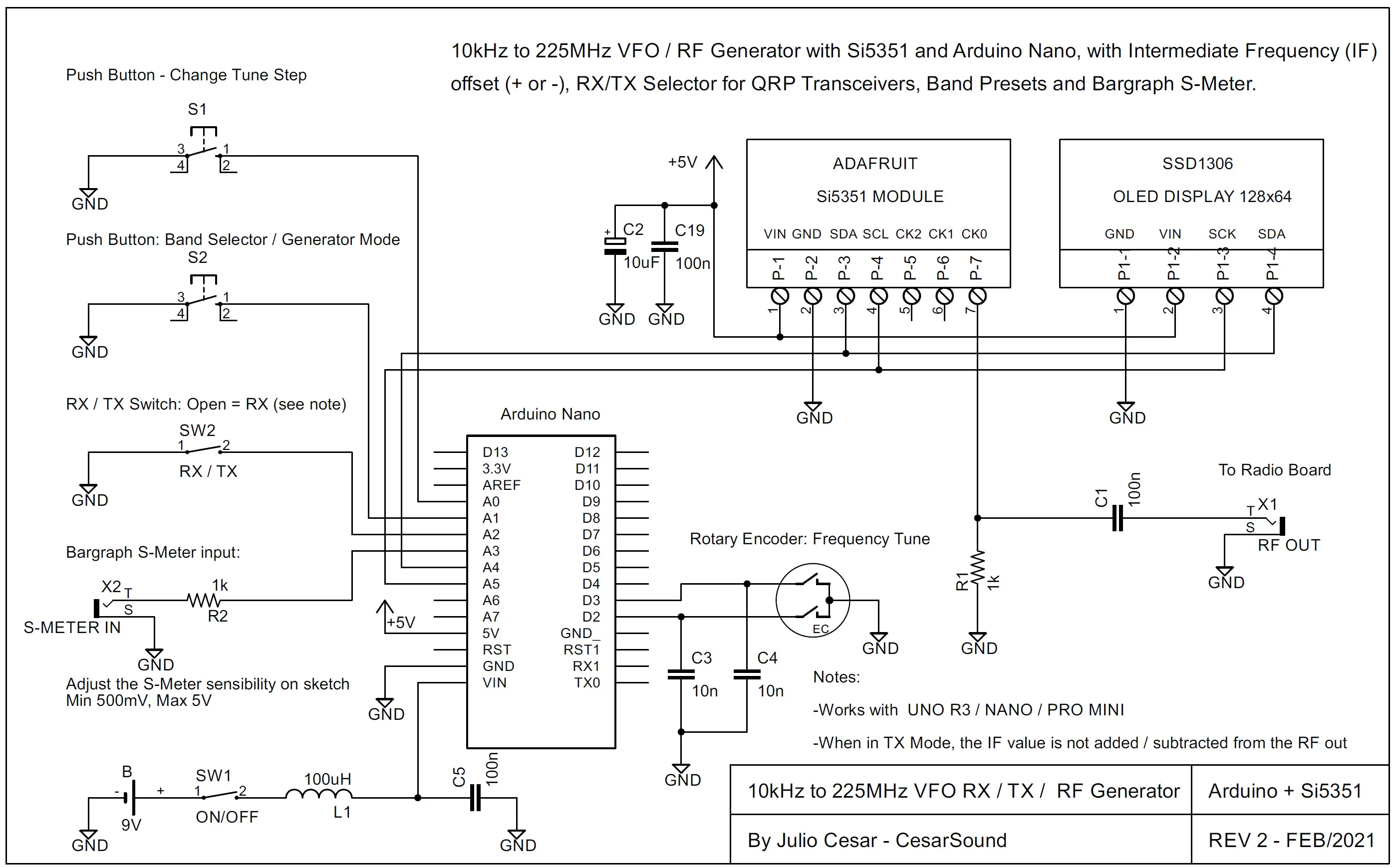
- Follow the schematics to wire the Arduino, Display, Si5351 module, rotary encoder, etc.
- Power up the Arduino.
- Rotate the rotary encoder to tune up or down the frequency.
- Push the push button 1 to change the frequency step tuning. The steps available are 1Hz, 10Hz, 1kHz, 5kHz, 10kHz and 1MHz.
- Push the push button 2 to browse (select) the 20 band presets or enter the generator mode.
- Turn on/off the switch SW 2 to change from RX to TX mode. RX mode = SW 2 Open and TX mode = SW 2 Closed to GND. When in TX mode, the IF value is not added/sub from the RF out. This is ideal for use in Homebrew QRP Transceivers.
- Connect the S-Meter output signal from your radio to the X2 connector (S-Meter input). This input has adjustable sensitivity, the gain must be adjusted in Sketch, accepting signals from 500mV to 5V (max).
- Known Issue: if it freezes in the initialization text, comment (put a //) at the line 77 statup_text ();
-It is possible to change the followings items on sketch:
#define IF 455 //Enter your IF frequency, ex: 455 = 455kHz, 10700 = 10.7MHz, 0 = to direct convert receiver or RF generator, + will add and - will subtract IF offfset.
#define BAND_INIT 7 //Enter your initial Band (1-21) at startup, ex: 1 = Freq Generator, 2 = 800kHz (MW), 7 = 7.2MHz (40m), 11 = 14.1MHz (20m).
#define XT_CAL_F 33000 //Si5351 calibration factor, adjust to get exatcly 10MHz. Increasing this value will decreases the frequency and vice versa.
#define S_GAIN 303 //Adjust the sensitivity of Signal Meter A/D input: 101 = 500mv; 202 = 1v; 303 = 1.5v; 404 = 2v; 505 = 2.5v; 1010 = 5v (max).
#define tunestep A0 //The pin used by tune step push button.
#define band A1 //The pin used by band selector push button.
#define rx_tx A2 //The pin used by RX / TX selector switch, RX = switch open, TX = switch closed to GND. When in TX, the IF is not considered.
#define adc A3 //The pin used by Signal Meter A/D input.
About the Rotary Encoder used in this project:I used the low-cost EC11 - 15mm rotary encoder (photo below), which can be purchased on Aliexpress in batches of 5 units. Note that this encoder has a blue plastic base and has 5 pins, 3 for the encoder and 2 for the push switch. This worked perfectly with the project. If the encoder action is inverted (it decreases when turning clockwise), simply flip (invert) the connection of the pins that go to D2 and D3. There are other types of encoders, some come with a built-in board, which can be tested here, but I have not tested them. In some cases, it may be necessary to include 2x 10k OHMM pullup resistors between +5v and pins D2 and D3.
This project is being sold on eBay and Aliexpress as a CLONE, already assembled including internal rechargeable battery. In case anyone is interested, this is the picture of it.
Disclaimer: The author of this project has no connection or any responsability with the sale of this assembled product. This product is not a complete radio transceiver, as described in the sales ad, it works only as a VFO / Continuous RF Generator.
Disclaimer:- The author of this project has no responsibility for the products (clones) being traded via China, as the manufacture and sale of these products has no connection with the author. This project is open source and is not intended for commercial profit.
- The author of this project reserves the right to change, modify or do corrections to the hardware and/or software at any time without notice or obligation to persons who already assembled it.
- Don't expect this project to perform as well or better than professional and commercial equipments, this is an amateur DIY home project that aims at the personal satisfaction of setting up at home and seeing it work beyond the learning that this activity provides.
Julio Cesar - CesarSound - ver 2.0 - Feb/2021.


Comments