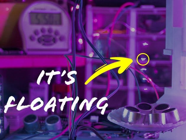
If you have ever worked with ultrasonic modules, for example, SRF05, you have noticed that two ultrasonic sensors are used in this group of modules, one to send waves and the other to receive that using the same wave travels back and forth projects easily. Sensors are made, if you disassemble these sensors, two letters R or T are printed on the back of these sensors. We need a T or Transmitter to make this project. The R Type is the receivers.
The L298N driver module is normally used to start DC motors, but as you will see later in this project we will use this module differently. This module has four outputs (out1, out2, and out3)., out4) that we will use out1 and ou2 outputs. In this project, using Arduino, the first 5v pp are applied to the driver module and then converted to 25v pp, and transmitters are applied.
Arduino board with Atmega328 processor, the codes we need for this project are programmed inside this microcontroller and will be applied to the driver using A0 and A1 outputs, which are our analog outputs.
To power the L298N module, we will need a 12-volt power supply, so using this module, we can easily convert the 3.7-volt voltage of ordinary batteries to 12-volt.
Note: Note that with an input of 3.5 or 3.7 volts in this module, we will receive a maximum output of 37 volts, so before connecting the module to the circuit with a voltmeter, measure the output and use the potentiometer in the output module. Set to the desired voltage.
When you connect the transducers to the driver, you will hear a quiet but annoying sound in the long run. This means that the device is working.
- Arduino A0 ====> IN1 L298
- Arduino A1 =====>IN2 L298
- L298 out1 =====> Ultrasonic transmitter
- L298 out2 =====>Ultrasonic transmitter


_ztBMuBhMHo.jpg?auto=compress%2Cformat&w=48&h=48&fit=fill&bg=ffffff)


_3u05Tpwasz.png?auto=compress%2Cformat&w=40&h=40&fit=fillmax&bg=fff&dpr=2)
Comments
Please log in or sign up to comment.