

Hardware components | ||||||
 |
| × | 1 | |||
 |
| × | 1 | |||
| × | 2 | ||||
| × | 2 | ||||
| × | 1 | ||||
 |
| × | 2 | |||
 |
| × | 1 | |||
 |
| × | 1 | |||
 |
| × | 1 | |||
 |
| × | 1 | |||
 |
| × | 1 | |||
 |
| × | 2 | |||
 |
| × | 1 | |||
 |
| × | 1 | |||
Hand tools and fabrication machines | ||||||
 |
| |||||
I've always enjoyed building and creating things, so I've decided to created props and replicas from objects found within movies and video games. Bringing a virtual object into reality, then sharing my techniques with those who have similar interests.
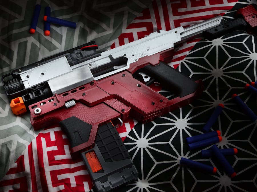
My latest and greatest creation is the Kang Tao, a smart gun featured in the upcoming video game Cyberpunk 2077. To create such a complex object, a 3D printer was used to achieve the aesthetics and mechanical fitment of parts.
A static object would be too easy though, I wanted a challenge. So I designed it as a functional Nerf Blaster.
To achieve this functionality, It needed to control a solenoid and ESCs for brushless motors. Relays and time delays etc would be too cumbersome and so an Arduino was a more practical solution.
This write up will be focused on the Arduino and electrica circuit aspect of this project (since this is an Arduino site). I labelled this 'easy' as the Arduino portion is quite simple. The mechanical design and 3D printing is advanced though. If you want to control a Brushless ESC, Brushless Motors and Solenoid with Arduino for Nerf Blasters, this guide is for you!
CAD Design, 3D Printing etc are explained here:http://nerfhaven.com/forums/topic/28493-cyberpunk-2077-kang-tao-3d-printed-nerf-gun/
Video build tutorials here: https://www.youtube.com/channel/UCP3j3nmdL5VLFy1indyyzAA/featured?view_as=subscriber
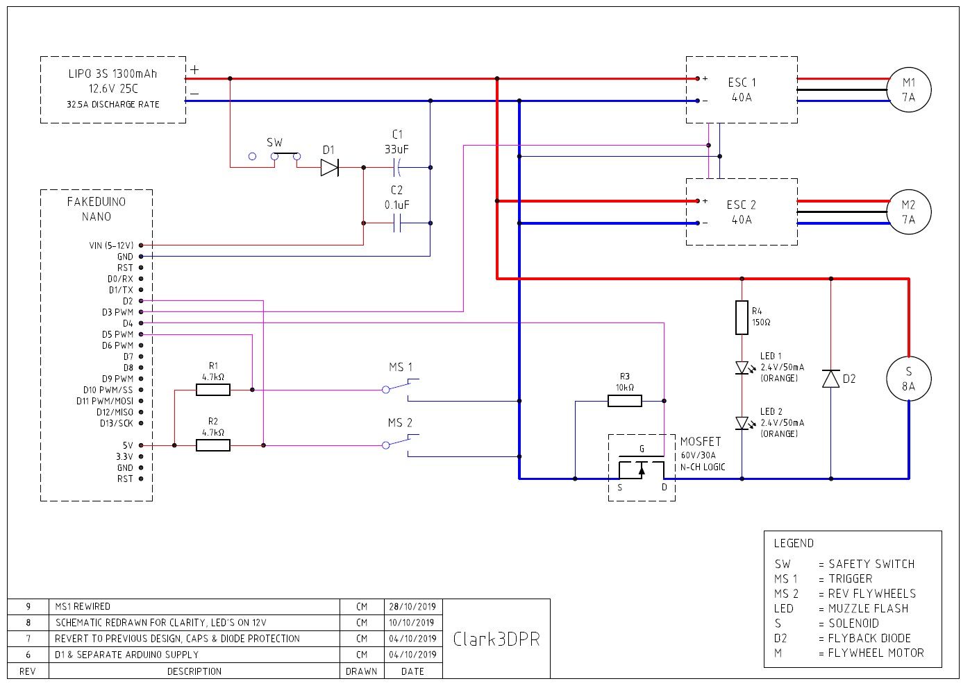
The schematic (refer schematic section) was drawn to illustrate how everything is connected. An Arduino Nano is used because of it's small size. This should work with a Uno and others too.
Refer to schematic for the below terminologies MS1, C2 etc.
Refer to Code section on explanation of how the code works.
Triggers with Flywheels & SolenoidThe way the code works, is that when MS2 (secondary microswitch trigger) is held, the brushless motors rev up.
When MS1 (primary microswitch trigger) is pressed or held, a signal is sent to the MOSFET gate to fire the Solenoid (S) repeatedly. The solenoid pushes the Nerf dart out of the mag and into the flywheels (M1 & M2) which then accelerate the dart out of the barrel.
However, MS1 only activates while MS2 is held. This helps prevent jams in case a dart gets pushed into non-spinning flywheels. In the code (refer code section), it is where '&&' is used.
Power supplied to the brushless motors and solenoid do not travel through the microswitches. This means you do not need high current rated microswitches.
Brushless MotorsI'm not going to explain how brushless differs from brushed motors here, you can search for some great explanations.
There are inrunner and outrunner brushless motors. You want an outrunner motor since they are flatter in shape so you don't have ugly cans sticking out the side of your Nerf blaster. Outrunner motors also have a portion of the external can rotate with the shaft. This makes it easy to 3D print flywheels to go over the motor.
Get a motor with rear mounting holes.
Voltages of motors should handle at least 12.6V (3s lipo).
Current of motor should not exceed Brushless ESC current rating.
Power of motors should be >60W. This project uses 12.6V supply voltage x measured 7A motor draw = ~80W each.
RPM of brushless motors should be ~25k and are determined by kV rating x Voltage. This project uses 2600kV motors @ 12.6V. Therefore 2600 x 12.6 = ~32, 760RPM. I only run the motors at half throttle and darts fly 25m / 82ft!
Brushless ESCsThese basically control the power of the brushless motors.
Brushless motors don't work with brushed ESCs, get brushless.
You need one ESC per motor. Otherwise the back EMF from two motors connected to one ESC will mess up the ESC timing and damage said ESC and / or motors.
Current rating of ESC needs to be higher than current draw of motor. Motor in this case was measured at 7A each. Recommend ESC is 20A or higher.
Voltage rating of ESC needs to be at least 12.6V (3s Lipo).
ESC does not need a built-in BEC. You can use 'OPTO' ESCs. If you have an ESC with BEC, connect the ground and signal cables to Arduino as shown in the schematic. Do NOT connect the ESC 5V Red cable to anything. (Unless you have a specific purpose for it and know what you're doing).
BatteryA single battery to power everything. I recommend using a XT60 connector.
Voltage is 12.6V 3S Lipo Battery.
Capacity is 1300mAH minimum recommended.
Current Discharge Rating of battery should be enough for the power draw of all loads. In this project, load current is ~25A.
Max discharge rate of battery is calculated by Discharge Rate (25C) x Capacity in Ah (1, 300mAh = 1.3Ah).
Therefore 25 x 1.3 = 32A max discharge rate for the battery. You should be able to find these numbers in the battery specs.
MOSFETPowering a 12V / 8A Solenoid straight from an Arduino will cause magic smoke (Arduino dies). Solution? MOSFET.
The power MOSFET is used as an on / off switch for the Solenoid. It basically interrupts the ground that powers the Solenoid. This is known as a N-Channel MOSFET. Make sure you get a N-Channel.
The MOSFET knows when to turn on and off because of a signal sent to the MOSFET gate pin from an Arduino output pin (D4 in this case). Arduino's put out 5V, and the gate should be fully on at 5V. For this to work it needs to be a Logic Level MOSFET.
Current draw from Solenoid is rated at 8A. Make sure the MOSFET has a higher max current rating. This project uses a 30A max rated MOSFET.
Voltage though the MOSFET is 12.6V to power the solenoid. This MOSFET is rated at 60V max which is plenty of headroom.
Temperature of the MOSFET is less than 35°C in this case. This is achieved because the MOSFET is rated for 30A, though there is only ~8A of load being pulled through it. The other reason is the load (Solenoid) is only powered on momentarily before switching off, instead of powered on constantly. A heat sink is not necessary in this case.
SolenoidThis pushes the dart into the flywheels. All you want is a 12V rated Solenoid with 35mm stroke length. Shorter strokes will not push the full length type Nerf darts far enough.
Upgrade it's spring to 0.9mm diameter wire, 14mmOD & 40mm length to prevent jams.
Because the Solenoid is powered on momentarily as opposed to constantly, it should only get mildly warm ~40°C and therefore not require cooling.
These solenoids are relatively cheap and generic. They can be found on Ebay, Aliexpress etc.
Safety SwitchSW safety switch is simply a 2 position slider switch. It has 3 contacts, though only 2 are used. Powers off Arduino when safety is on, preventing flywheels & solenoid from activating.
Protection CircuitryThis section explains how to prevent frying your electronics!
C1 33μF (100μF recommended) & C2 100nF (0.1µF) reduces voltage fluctuation to the Arduino power input.
Caution: C1 is polarity sensitive, striped side is negative, else it goes bang!
D1 prevents reverse voltage to Arduino VIN. Take note of it's polarity.
D2 is a fly-back / freewheeling diode. It prevents the solenoid (or other inductors) from creating back EMF. This back EMF could otherwise damage the MOSFET. Take note of it's polarity.
R1 & R2 are 4.7kΩ pull-up resistors for MS1 & MS2. This prevents floating voltage at the microswitches.
R3 is a 10kΩ pull-down resistor to prevent floating voltage at the gate of the MOSFET.
R4 is a 150kΩ for the optional LED's. My LED's are 2 in series at 2.4V / 50mA each. Your resistor value may vary. These LED's flash on and off in sync with the solenoid to replicate muzzle flash!
Video explanation & test firing below!
That sums up this guide, any questions leave a comment below :)
File Download So You Can Print It Yourself!UPDATE: Here is the link to the Thingiverse files, enjoy!
https://www.thingiverse.com/thing:3984125


Comments